Class 12 PCM . Physics . Physics Part I . Alternating Current
Chapter 7: Alternating Current
Ch 7
Physics
Class 12 PCM
Introduction
Alternating Current: Basic Idea
Direct current (DC) — A current that does not change direction with time.
- Alternating current (AC): A current that varies with time and reverses direction periodically.
- Alternating voltage: A voltage that varies with time; household mains voltage varies sinusoidally.
- Use of AC: Most electrical energy supplied by power companies is transmitted and distributed as AC.
- Why AC is preferred: Transformers change AC voltage efficiently, enabling economical transmission over long distances.
- Application: AC circuit properties are used in devices such as radios when tuning to a station.
| Feature | DC | AC |
|---|---|---|
| Direction | Does not reverse with time | Reverses periodically |
| Variation | Does not alternate direction | Voltage and current vary with time, often sinusoidally |
| Voltage conversion | Not as conveniently converted to different voltages | Voltage can be changed efficiently using transformers |
AC Voltage Applied to a Pure Resistor
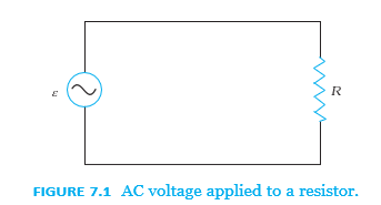
- Sinusoidal voltage: For a source with peak voltage and angular frequency , the instantaneous voltage is .
- Current through the resistor: Kirchhoff’s loop rule gives , so the current is sinusoidal too.
- Current amplitude: The peak current is , giving .
- Ohm’s law: For a resistor, Ohm’s law applies to both AC and DC; using rms values, .
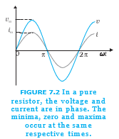
- Phase: Voltage and current reach zero, maximum and minimum together; they are in phase.
Average Power and RMS Values
- Average over a cycle: The average of a periodic quantity over period is .
- Current average: A sinusoidal AC current has positive and negative values that cancel over one complete cycle, so its average current is zero.
- Heating: Average current zero does not mean zero energy loss; Joule heating depends on , which is positive for either current direction.
- Instantaneous power: In a resistor, .
- Mean-square factor: Over one cycle, , so average power is .
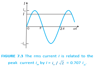
RMS current — The root mean square (rms), or effective, current is the DC current that produces the same average power loss in a resistor.
For sinusoidal current with peak value .
For sinusoidal voltage with peak value .
Using rms values, AC power has the same form as DC power.
- AC voltage-current relation: Since , dividing by gives for rms values.
- Mains rating: The stated household line voltage of is an rms value; its peak voltage is .
- Measurement convention: AC voltage and current are customarily specified by their rms values.
Example: A Rated Light Bulb
- Given: A bulb is rated on a rms supply.
- Resistance: .
- Peak supply voltage: .
- RMS current: .
Quick recap
- AC varies with time and reverses direction; mains voltage is sinusoidal.
- Transformers make AC voltage conversion efficient and long-distance transmission economical.
- In a pure resistor, and are in phase, with .
- The average current over a cycle is zero, but average power is nonzero because heating depends on .
- For sinusoidal quantities, and .
- For a resistor, and using rms values.
Representation of Ac Current and Voltage by Rotating Vectors — Phasors
Phasors and Phase
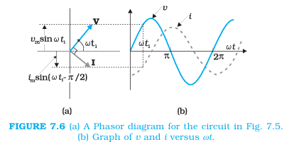
- Phasor: A rotating vector whose magnitude represents the peak value and whose vertical projection represents the instantaneous value of an alternating quantity.
- Phase: The relative angular position of voltage and current phasors shows their phase difference; phasor diagrams simplify AC circuit analysis.
AC Voltage Applied to a Pure Inductor
Using , the current is sinusoidal and lags the voltage by one-quarter cycle.
Inductive reactance — Inductive reactance, , is the opposition an inductor offers to alternating current.
Phase and Power in a Pure Inductor
- Phase: Current lags voltage by radians, or one-quarter of a cycle.
- Time delay: Current reaches its maximum after voltage does, where .
- Instantaneous power: .
- Average power: The average of over a complete cycle is zero; hence an ideal inductor consumes zero average power.
Example 7.2
- Given: , and source rms voltage .
- Reactance: .
- Rms current: .
Quick recap
- A phasor’s length represents peak value; its rotating projection represents the instantaneous AC value.
- For a pure resistor, voltage and current are in phase.
- For a pure inductor, : current lags voltage by one-quarter cycle.
- Inductive reactance is and is measured in ohms.
- The current amplitude is ; rms current is .
- An ideal inductor consumes zero average power over a complete cycle.
Ac Voltage Applied to a Capacitor
A Capacitor in DC and AC Circuits
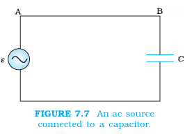
Purely capacitive AC circuit — An AC circuit containing a capacitor as its only circuit element.
What the capacitor does
- With DC: Current flows only while the capacitor charges; once fully charged, the current becomes zero.
- With AC: The capacitor repeatedly charges and discharges as the current reverses each half-cycle, so charge continues to flow.
- Voltage across the capacitor: At any instant, it is related to the charge on its plates by .
Current and Capacitive Reactance
Deriving the AC current
- Source voltage: For , the loop rule gives .
- Current: Using , the current varies as a cosine and can be written as a sine with a phase shift of .
- Current amplitude: .
Capacitive reactance — The opposition a capacitor offers to alternating current; it plays the role of resistance in a purely capacitive AC circuit.
Use these relations for a sinusoidal AC source.
Properties of capacitive reactance
- Unit: The SI unit is the ohm (), the same as for resistance.
- Frequency dependence: Since , increasing frequency decreases .
- Capacitance dependence: Increasing decreases ; thus, for fixed voltage amplitude, current amplitude increases.
Phase and Power
Voltage-current phase relationship
- Capacitor: Current leads voltage by (90°), reaching its maximum one-quarter of a period earlier.
- Phasors: The current phasor is ahead of the voltage phasor as they rotate counterclockwise.
| Element | Current relative to voltage |
|---|---|
| Capacitor | Current leads by . |
| Inductor | Current lags by . |
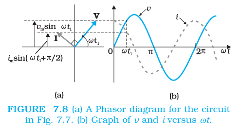
The cycle average is zero because the average of over a full cycle is zero.
Applications and Example
Lamp in series with a capacitor
- DC connection: After the capacitor charges, no current flows and the lamp does not glow; reducing does not change this final outcome.
- AC connection: Current flows through the circuit, so the lamp glows. Reducing raises and reduces current, making the lamp dimmer.
Numerical example
- Given: , (rms), and .
- Reactance: .
- Current: (rms), so .
- If frequency doubles: halves and the current doubles; current still leads voltage by .
How does reducing the capacitance affect an AC lamp circuit?
Quick recap
- A DC capacitor passes current only while charging; after full charge, current is zero.
- In AC, the capacitor repeatedly charges and discharges, allowing alternating current.
- Capacitive reactance is and is measured in ohms.
- The current amplitude is ; current leads voltage by .
- The average power supplied to an ideal capacitor over a complete cycle is zero.
- Increasing frequency or capacitance lowers reactance and increases current for a fixed voltage.
Ac Voltage Applied to a Series Lcr Circuit
Series LCR Circuit
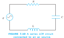
Series LCR circuit — A resistor, inductor and capacitor connected in series to an AC source carry the same instantaneous current.
Circuit equation
- Source voltage: Let ; the current is common to all three components.
- Kirchhoff’s loop rule: The instantaneous source voltage equals the sum of the component voltages.
Phasor-Diagram Solution
Current and component voltages
- Current: Write , where is the phase of current relative to the source voltage.
- Resistor: is in phase with the current; its amplitude is .
- Inductor: leads the current by ; its amplitude is .
- Capacitor: lags the current by ; its amplitude is .
Reactances determine the amplitudes of the inductor and capacitor voltages.
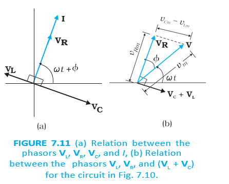
The resistor voltage and the net reactive voltage are perpendicular phasor components. Their vector sum gives the source-voltage amplitude.
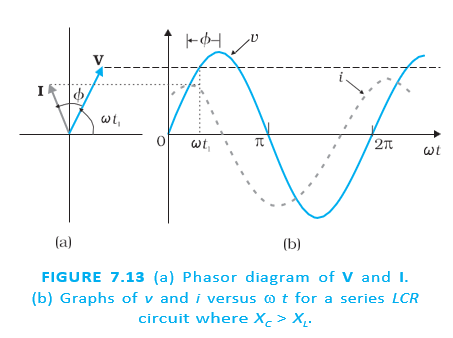
The angle between the source-voltage phasor and the resistor-voltage phasor (parallel to current) gives the current’s phase relative to the source.
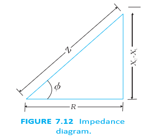
| Condition | Circuit behaviour | Current relative to source voltage |
|---|---|---|
| Predominantly capacitive; | Current leads | |
| Predominantly inductive; | Current lags |
Steady state and transient response
- Phasor solution: Gives the steady-state current after the initial effects have died away; it does not specify the initial condition.
- General response: It is the sum of the transient and steady-state solutions.
- Transient response: A transient solution can exist even when the applied voltage is zero; it dies out after sufficient time, leaving the steady-state behaviour.
Resonance
Resonance — In a driven oscillating system, resonance occurs when the driving frequency matches its natural frequency, producing a large response.
Resonance in a series LCR circuit
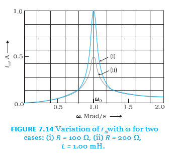
- Condition: Resonance occurs when .
- At resonance: The inductive and capacitive voltages cancel, so and the current amplitude is maximum.
- Frequency: The resonant angular frequency depends on and , not on .
- Requirement: Both and must be present for their reactances to cancel; an or circuit alone cannot resonate.
At resonance the source voltage appears across the resistance, giving the maximum current.
Applications and example
- Radio/TV tuning: Vary the tuning-circuit capacitance so its resonant frequency matches the desired station’s signal; the matching signal then produces maximum current.
- Illustrative values: For and , . With the same source, the resonant current for is twice that for .
Worked Example: Series RC Circuit
Given: , , rms,
- Capacitive reactance: .
- Impedance and current: ; hence .
- Component voltages: and .
- Resolve the apparent paradox: Although arithmetically, these voltages are out of phase. Their phasor sum is .
Do not add AC voltage amplitudes or rms voltages as ordinary numbers when they have different phases; add their phasors.
State the resonance condition and resonant angular frequency of a series LCR circuit.
When does the current lead or lag the source voltage in a series LCR circuit?
Why can the voltages across a resistor and capacitor add to more than the source voltage arithmetically?
Quick recap
- In a series LCR circuit, the same current passes through , and ; their voltages add as phasors.
- The impedance is and the current amplitude is .
- If , current leads the source; if , current lags.
- Resonance occurs at , where and current is maximum.
- Only a circuit containing both and can have their reactances cancel and exhibit resonance.
- At resonance, radio tuning selects a signal by adjusting capacitance so the circuit’s resonant frequency matches it.
Power in Ac Circuit: the Power Factor
Instantaneous and Average Power in an AC Circuit
- AC voltage and current: For a series RLC circuit, and , where .
- Phase angle: ; its sign indicates whether current leads or lags the voltage.
- Instantaneous power: The product of voltage and current varies during each cycle: .
- Average power: The time-dependent cosine term averages to zero over a complete cycle; only the constant term contributes to average power.
Here and are rms values. The power factor is .
Power factor — The cosine of the phase difference between AC voltage and current, ; it determines what fraction of apparent power is average power.
Power in Different AC Circuits
| Circuit | Phase and power factor | Average power |
|---|---|---|
| Pure resistor | , so | Maximum power for the given voltage and resistance; . |
| Pure inductor or capacitor | , so | No average power is dissipated, although current flows; this is called wattless current. |
| Series RLC circuit | Average power is dissipated only in the resistor; . | |
| Series RLC at resonance | , so and | Impedance is and power is maximum: . |
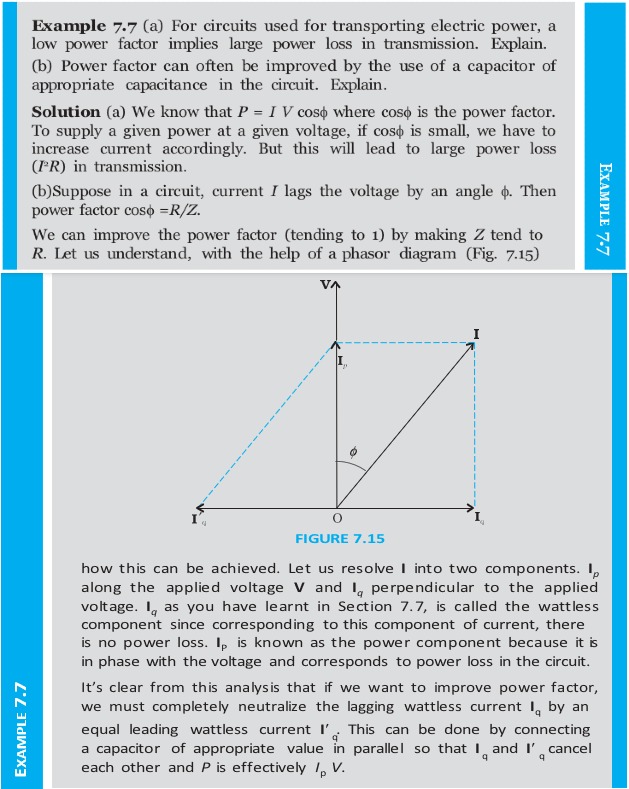
A flowing AC current does not always mean average power is consumed: in a purely inductive or capacitive circuit, voltage and current are in quadrature and the average power is zero.
Worked Examples: Power and Resonance
Series RLC example at 50 Hz
- Given: , , , and .
- Reactances: and .
- Impedance and phase: ; . The negative phase means current lags voltage.
- Power and power factor: ; and .
For a series RLC circuit, resonance occurs when .
Same circuit at resonance
- Resonant frequency: With the example's and , and .
- Impedance and current: At resonance, and the rms source voltage is , giving .
- Power: , greater than the power at 50 Hz in the previous example.
Application: Metal Detector
How an AC metal detector signals metal
- A coil and capacitor are tuned to resonance.
- Metal entering the coil changes the circuit impedance.
- The resulting current change is detected by electronic circuitry.
- The detector sounds an alarm.
Quick recap
- Average AC power is , with and as rms values.
- The power factor depends on the voltage-current phase difference.
- Only the resistor dissipates average power in a series RLC circuit.
- Pure inductive or capacitive current is wattless: its average power is zero.
- At resonance, , , the power factor is one and power is maximum.
- An AC metal detector detects metal through its effect on resonance, impedance and current.
Transformers
Transformer: Principle and Construction
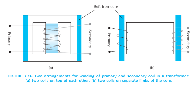
Ideal Transformer Relations
The minus sign indicates the direction of induced emf according to Lenz’s law.
Power and Current in an Ideal Transformer
Combining power conservation with the voltage ratio gives the current ratio.
Step-Up and Step-Down Transformers
Example: Step-Up Transformer
- Turns ratio: For and , .
- Output: An input of at gives an ideal output of at .
Energy Losses in Real Transformers
- Energy losses: Real transformers lose energy through flux leakage, resistance in the windings, eddy currents in the core, and hysteresis.
- Reducing losses: Good core design limits flux leakage; thick wire reduces winding resistance losses, laminated cores reduce eddy currents, and low-hysteresis materials reduce heating.
Transformers in Power Transmission
State the voltage and current relations for an ideal transformer.
Name four energy losses in a real transformer and one way to reduce each.
Quick recap
- A transformer changes AC voltage through mutual induction between primary and secondary coils.
- For an ideal transformer, and .
- Ideal input and output powers are equal: .
- A step-up transformer has and increases voltage while reducing current; a step-down transformer does the reverse.
- Real-transformer losses include flux leakage, winding resistance, eddy currents and hysteresis.
- Stepping up voltage for transmission reduces current and losses; voltage is stepped down before reaching homes.
Summary
AC in a Resistor
AC through a resistor — In a pure resistor, alternating current and applied voltage are in phase.
- Voltage and current: If , then .
- Peak current: .
- Phase: Current and voltage reach their peaks and zero values together.
RMS Values and AC Power
RMS value — The rms value of an AC current or voltage produces the same average heating effect as an equivalent DC value.
For sinusoidal AC, rms values are the peak values divided by .
- Numerical factor: and .
- Average resistor power: .
- Usual ratings: AC voltage and current ratings ordinarily refer to rms values. A outlet has peak voltage .
- Power rating: An AC component’s stated power rating refers to its average power.
AC Through a Pure Inductor
Inductive reactance — Inductive reactance is the opposition an inductor offers to alternating current.
- Current: For , .
- Reactance and peak current: and .
- Phase: Current lags voltage by .
- Average power: A pure inductor consumes zero average power over a complete cycle.
AC Through a Pure Capacitor
Capacitive reactance — Capacitive reactance is the opposition a capacitor offers to alternating current.
- Current: For , .
- Reactance and peak current: and .
- Phase: Current leads voltage by .
- Average power: A pure capacitor consumes zero average power over a complete cycle.
Series RLC Circuit
Impedance — Impedance is the total opposition to current in a series RLC circuit, combining resistance and net reactance.
For applied voltage , the current is .
- Average power: , where and are rms values.
- Power factor: measures how close the circuit is to expending maximum power.
- Power sign: Power consumed in an AC circuit is never negative.
Wattless Current and Power Dissipation
Wattless current — A wattless current flows in a purely inductive or capacitive circuit where average power dissipation is zero.
- Condition: For a pure inductor or capacitor, even though current flows.
- Energy: Ideal inductors and capacitors store and return energy; only resistance dissipates energy in an AC circuit.
Phasors and Phase Addition
Phasor — A phasor is a rotating vector used to represent the amplitude and phase of a sinusoidally varying quantity.
- Rotation: A phasor rotates about the origin with angular speed ; its magnitude represents the peak value.
- Use: Phasor diagrams simplify addition of AC quantities with different phases.
- Important: Voltage and current are scalars, not true vectors; phasors are a mathematical aid for combining their amplitudes and phases.
- RC example: For resistor and capacitor voltages and , because they are out of phase—not simply .
Transformer
Transformer — A transformer has primary and secondary coils wound on an iron core and changes AC voltage.
- Coils: The primary has turns and the secondary has turns.
- Voltage relation: .
- Current relation: ; current varies inversely with the turns ratio.
- Step-up: If , then and .
- Step-down: If , the transformer steps the voltage down.
- Energy: Increasing voltage does not violate conservation of energy; the secondary current is reduced correspondingly.
Key Quantities, Dimensions and Units
| Quantity | Symbol | Dimensions | Unit / relation |
|---|---|---|---|
| RMS voltage | ; | ||
| RMS current | ; | ||
| Inductive reactance | ; | ||
| Capacitive reactance | ; | ||
| Impedance | ; depends on circuit elements | ||
| Resonant angular frequency | ; | ||
| Quality factor | Dimensionless | ||
| Power factor | Dimensionless | , where is the phase difference between applied voltage and current |
Resonance and Quality Factor
Resonance — In a series RLC circuit, resonance occurs when the inductive and capacitive reactances are equal.
Both an inductor and a capacitor must be present for resonance.
- At resonance: The inductor and capacitor effects cancel; impedance is , current is in phase with voltage, and the power factor is .
- Quality factor: For a series RLC circuit, .
Other Important Points
- AC ampere: One ampere rms is the alternating current that produces the same average heating as one ampere of DC under the same conditions.
- Why heating defines AC current: AC reverses direction, so the attraction between parallel AC currents averages to zero; Joule heating is independent of current direction.
- Motor: Electrical energy is the input and mechanical energy is the output.
- Generator: Mechanical energy is the input and electrical energy is the output.
- Energy conversion: Motors and generators transform energy from one form to another.
Why is current in a pure inductor or capacitor called wattless?
State the resonance condition and resonant angular frequency for a series RLC circuit.
How are transformer voltage and current related to the turns ratio?
Quick recap
- In a resistor, AC voltage and current are in phase; rms values equal peak values divided by .
- Inductor current lags voltage by ; capacitor current leads voltage by .
- Series RLC impedance is and average power is .
- Pure inductors and capacitors have zero average power; resistance is the element that dissipates energy.
- Phasors help combine AC quantities according to phase; voltage and current themselves are scalars.
- RLC resonance requires both and , with and .
- Transformer voltage follows the turns ratio, while current follows its inverse.
Physics — ALL CHAPTERS
1
Electric Charges And Fields
2
Electrostatic Potential And Capacitance
3
Current Electricity
4
Moving Charges And Magnetism
5
Magnetism And Matter
6
Electromagnetic Induction
7
Alternating Current
8
Electromagnetic Waves
1
Ray Optics And Optical Instruments
2
Wave Optics
3
Dual Nature Of Radiation And Matter
4
Atoms
5
Nuclei
6
Semiconductor Electronics: Materials, Devices And Simple Circuits