Class 12 PCM . Physics . Physics Part I . Electromagnetic Induction
Chapter 6: Electromagnetic Induction
Ch 6
Physics
Class 12 PCM
Introduction
Electricity and Magnetism
- Relationship: Moving electric charges produce magnetic fields, linking electricity and magnetism.
- Induction: Faraday and Henry showed that changing magnetic fields can generate electric currents.
Faraday and Henry’s Experiments
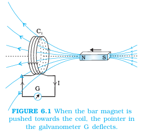
Magnet and Coil
- Motion: Pushing a magnet towards a coil causes a galvanometer deflection, showing that current is induced.
- No motion: Holding the magnet stationary produces no deflection; the induced current lasts only while the magnet moves.
- Reversal: Pulling the magnet away reverses the deflection. Moving a south pole instead of a north pole also reverses the deflection for the same motion.
- Speed: Faster magnet motion produces a larger deflection and therefore a larger induced current.
- Relative motion: Moving the coil while keeping the magnet fixed produces the same effects; relative motion changes the magnetic influence through the coil.
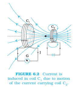
Two Coils in Relative Motion
- Setup: A steady current in coil produces a steady magnetic field; coil is connected to a galvanometer.
- Approach and withdrawal: Moving towards induces current; moving it away induces current in the opposite direction.
- Relative motion: The deflection occurs only while the coils move relative to each other. Moving instead gives the same effects.
Stationary Coils with a Changing Current
- Switching on: Pressing the key in the circuit of causes a momentary galvanometer deflection in .
- Steady current: If the key remains pressed, the galvanometer returns to zero; a steady current in causes no continuing induced current.
- Switching off: Releasing the key causes another momentary deflection, in the opposite direction.
- Iron core: Inserting an iron rod along the coils increases the deflection substantially.
- Core idea: An induced current appears when the magnetic flux through a coil changes, whether the change is caused by motion or by a changing current in another coil.
Magnetic Flux
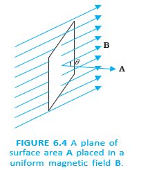
Magnetic flux — Magnetic flux measures the magnetic field passing through a surface.
Here is the angle between the magnetic field and the area vector , which is normal to the surface.
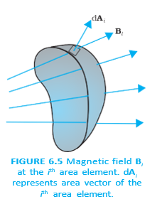
Divide the surface into small area elements and add the flux contributions from the field at each element.
Magnetic Flux: Key Properties
- Unit: The SI unit is the weber (), equivalent to tesla metre squared ().
- Nature: Magnetic flux is a scalar quantity.
Quick recap
- Changing magnetic flux through a conducting coil can induce current.
- Magnet motion, coil motion, or a changing current in a nearby coil can change flux.
- Induced current persists only while the flux changes; reversing the change reverses the current direction.
- For a uniform field, , where is measured from the area vector.
- For a curved surface or nonuniform field, add the contributions over all area elements.
- Magnetic flux is a scalar measured in webers (), equal to tesla metre squared.
Faraday’s Law of Induction
Changing Magnetic Flux and Induced EMF
- Changing flux: A change in magnetic flux through a circuit produces an induced emf.
- Causes: Flux can change through variations in magnetic field, loop area, or the angle between the field and area vector.
Faraday’s Law
The signed induced emf is given by:
Coils with Multiple Turns
For a coil with turns:
Ways to Change Magnetic Flux
Here, is the angle between the magnetic field and the area vector.
Applying Faraday’s Law
Use the magnitude of the flux change; for a circuit of resistance , apply Ohm’s law.
Worked application: square loop
- Given: A square loop has side , resistance , and is in a field at to its area vector. The field falls to zero in .
- Initial flux: ; final flux is zero.
- Induced emf: .
- Induced current: .
- Note: A steady background field, such as Earth’s field over this short interval, does not induce emf.
Worked application: rotating coil
- Given: A -turn circular coil of radius and resistance is rotated through in in a horizontal field of .
- Flux change per turn: The coil’s area is ; its flux changes from to , so .
- Induced emf: .
- Induced current: .
- Instantaneous values: These are average estimates over the rotation; instantaneous emf and current depend on the coil’s rotation speed at that moment.
A magnetic field by itself does not guarantee induced emf: the magnetic flux must change with time.
Quick recap
- Induced emf is produced by a changing magnetic flux through a circuit.
- Faraday’s law is ; the negative sign indicates direction.
- For identical turns, .
- Flux can change by varying field strength, coil area, or the angle between field and area vector.
- A larger rate of flux change or more coil turns gives a larger induced emf.
- For a closed resistive circuit, induced current magnitude is .
Lenz’s Law and Conservation of Energy
Lenz’s Law
Lenz’s law — The polarity of induced emf is such that the current it produces opposes the change in magnetic flux that caused it.
Meaning and sign
- Statement: Heinrich Friedrich Lenz deduced this law in 1834.
- Opposition: The induced effect opposes the change in flux, not necessarily the magnetic field itself.
- Negative sign: The negative sign in Faraday’s law represents this opposition.
The negative sign indicates that the induced emf opposes the change in magnetic flux.
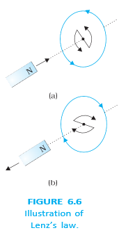
| Magnet motion | Flux change | Induced current (viewed from magnet side) | Coil’s near face and force |
|---|---|---|---|
| North pole approaches | Flux increases | Counter-clockwise | North pole; repels the magnet |
| North pole recedes | Flux decreases | Clockwise | South pole; attracts the magnet |
Open circuit
- Induced emf: An emf can appear across the open ends even when the circuit is incomplete.
- Current: No sustained current flows in an open circuit, but the emf’s polarity is determined by Lenz’s law.
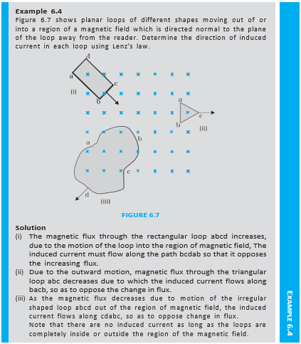
Lenz’s Law and Conservation of Energy
Energy in electromagnetic induction
- A magnet moves relative to a coil, changing the magnetic flux through it.
- The induced current produces a magnetic effect that opposes the magnet’s motion.
- An external agent must do work to move the magnet against this opposing force.
- The supplied energy is dissipated as Joule heating due to the induced current.
Why the induced effect must oppose the change
- If it aided the change: The magnet would accelerate and gain kinetic energy without an energy input.
- Consequence: Such motion could enable perpetual motion, violating conservation of energy.
- Correct case: The opposing magnetic force requires external work, and the energy is accounted for as Joule heat.
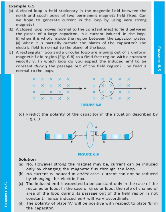
Do not say that induced current always opposes the magnetic field. It opposes the change in flux; when flux decreases, the induced effect may reinforce the field.
State Lenz’s law and explain the negative sign in Faraday’s law.
How does Lenz’s law agree with conservation of energy?
Quick recap
- Lenz’s law says the induced effect opposes the change in magnetic flux that produces it.
- The negative sign in Faraday’s law expresses this opposition.
- An approaching north pole induces a counter-clockwise current; the coil’s near face becomes north and repels it.
- A receding north pole induces a clockwise current; the coil’s near face becomes south and attracts it.
- An open circuit can have induced emf across its ends, although it has no sustained current.
- External work against the opposing force is dissipated as Joule heat, consistent with conservation of energy.
Motional Electromotive Force
Motional EMF in a Sliding Rod
Motional EMF — The emf induced when a conductor moves through a magnetic field is called motional emf.
Sliding-Rod Setup and Flux
- Setup: A rod of length slides at speed in a uniform, time-independent magnetic field perpendicular to the circuit.
- Changing area: As the rod moves, the loop area changes; if its width is , the magnetic flux is .
- Induction: The changing flux induces emf. For motion to the left, , so the emf magnitude is .
- Energy: In the idealised setup, friction causes no energy loss; the rod’s motion supplies energy to the induced current.
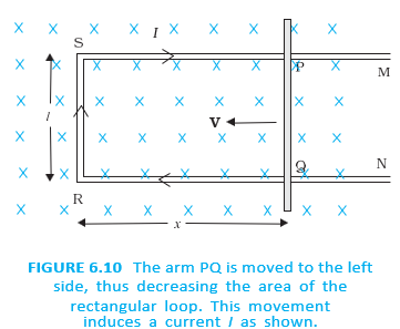
Faraday’s law gives the signed emf; for the stated motion its value is .
Lorentz-Force Explanation
- Force on charge: A charge moving with the rod experiences magnetic force of magnitude ; in the shown arrangement, the force is toward .
- Work across rod: The force acts along the rod, so moving a charge through length involves work .
- EMF: Since emf is work done per unit charge, .
- Scope: This force-based explanation applies to a moving conductor in a uniform, time-independent magnetic field.
Changing Field and a Stationary Conductor
- Stationary conductor: For a conductor at rest, , so the magnetic-force term vanishes and .
- Induced electric field: An emf in a stationary conductor with a changing magnetic field requires an electric field generated by the time-varying field.
- Key distinction: Electric fields due to static charges differ in properties from those produced by time-varying magnetic fields.
- Faraday’s insight: A changing magnetic field can affect stationary charges; electricity and magnetism are related.
For a stationary conductor, and only the electric-field force acts on its charges.
EMF in a Rotating Rod or Wheel
- Rotating rod: Rotation in a uniform magnetic field generates emf between the rod’s centre and outer end.
- Rotating spoke: A spoke of length rotating at angular speed in a field perpendicular to its plane develops axle-to-rim emf .
- Multiple spokes: Identical spokes connect the axle and rim in parallel, so their number does not change the emf between them.
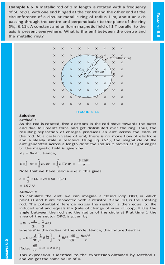
Use this for the emf between the axle and rim of a rotating spoke when the magnetic field is perpendicular to the plane of rotation.
A wheel has 10 spokes of length and rotates at in a field of . The wheel’s plane is normal to the horizontal component of Earth’s magnetic field. Find the axle-to-rim emf.
Quick recap
- A moving conductor in a magnetic field can develop motional emf: for the sliding rod.
- The sliding-rod emf follows from Faraday’s law because the enclosed magnetic flux changes.
- The magnetic force on moving charges gives and hence .
- A changing magnetic field generates an electric field that can induce emf in a stationary conductor.
- A rotating spoke produces axle-to-rim emf when the field is perpendicular to its plane of rotation.
- The number of identical spokes in parallel does not alter the axle-to-rim emf.
Inductance
Inductance: Meaning and Unit
- Definition: Inductance is the ratio of flux linkage to current, expressed as .
- Unit: The SI unit is the henry (H); inductance is a scalar quantity.
Mutual Inductance
- Meaning: Mutual inductance describes the flux linkage in one coil caused by current in a nearby coil.
- Reciprocity: For a pair of coils, ; mutual inductance depends on their geometry, separation, and relative orientation.
Mutual Inductance of Coaxial Solenoids
Example: Two Concentric Circular Coils
- Condition: A small coil of radius is coaxial with a larger coil of radius , with .
- Approximation: The larger coil’s field is nearly uniform across the small coil’s area: .
- Result: The mutual inductance is .
Induced EMF from Mutual Inductance
Coil 1 due to a changing current in coil 2.
Self-Inductance
For constant self-inductance.
Self-Inductance of a Long Solenoid
- Solenoid: A long solenoid of cross-sectional area , length , and turns per unit length has in air or vacuum.
- Magnetic core: With a material of relative permeability , its inductance is .
Energy Stored in an Inductor
Energy stored when current flows through inductance .
Magnetic Energy Density
- Energy density: The magnetic energy stored per unit volume in a field is in vacuum.
- Uniform solenoid: The energy density is also in the field inside a long solenoid in air.
Self and Mutual Effects in Two Coils
What is the difference between self-induction and mutual induction?
State the self-inductance and magnetic energy of a long solenoid.
Quick recap
- Inductance is flux linkage per current; its SI unit is the henry ().
- Mutual inductance obeys and depends on coil arrangement and medium.
- A changing current induces emf: mutual ; self-induced .
- A long solenoid has in air or vacuum; a magnetic core multiplies this by .
- An inductor stores magnetic energy .
- Magnetic energy density is , analogous to electric energy density .
Ac Generator
Principle and Construction
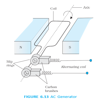
AC generator — A device that converts mechanical energy into electrical energy by electromagnetic induction, producing an alternating emf.
Main parts and operation
- Armature: A coil mounted on a rotor shaft; an external mechanical source rotates it in a uniform magnetic field.
- Orientation: The coil’s axis of rotation is perpendicular to the magnetic field.
- Flux change: Rotation changes the angle between the coil’s area vector and the field, changing magnetic flux and inducing emf.
- Connections: Slip rings and carbon brushes connect the rotating coil to the external circuit.
- Development: The development of the AC generator is credited to Yugoslav inventor Nicola Tesla.
Induced Emf in a Rotating Coil
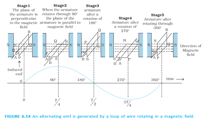
- Angle: For constant angular speed , with initial angle zero, .
- Effective area: The coil’s area perpendicular to the field is , so its magnetic flux changes as it rotates.
The peak emf occurs when the rate of change of flux is greatest.
- Extrema: The emf has maximum magnitude at and , where flux changes most rapidly.
- Alternation: The emf and current reverse direction periodically, producing alternating current (AC).
- Range: The instantaneous emf varies periodically between and .
Here is the frequency of revolution of the generator’s coil.
Do not confuse maximum emf with instantaneous emf: is the peak value, while varies with time.
Example: Maximum Voltage
Bicycle-driven coil
- Given: , , and .
- Calculation: .
- Answer: The maximum generated voltage is approximately .
Commercial Generators
| Type | Energy source / process | Example |
|---|---|---|
| Hydroelectric | Water falling from a height rotates the armature. | Water released from dams |
| Thermal | Heat produces high-pressure steam, which rotates the armature. | Coal or other heat sources |
| Nuclear power | Nuclear fuel supplies heat to generate steam for rotation. | Nuclear fuel |
- Mechanical input: Commercial generators use an external source to rotate the armature.
- Construction variation: In most generators, the coils remain stationary while electromagnets rotate.
- Output capacity: The lecture gives about as a typical modern AC generator capacity and notes generators can produce up to .
- Rotational frequency: The generator coil rotates at in India and in countries such as the USA.
Quick recap
- An AC generator converts mechanical energy into electrical energy through electromagnetic induction.
- Rotation changes the magnetic flux through the coil and induces an emf.
- For a coil with turns, peak emf is .
- The instantaneous emf varies sinusoidally between and .
- Hydroelectric, thermal and nuclear generators use different energy sources to drive rotation.
- The source states that the generator coil’s rotational frequency is in India and in countries such as the USA.
Summary
Magnetic Flux
- Definition: Magnetic flux through a plane surface is , where is the angle between the field and area vectors.
- Unit: Magnetic flux is a scalar measured in weber (Wb), equivalent to tesla metre squared.
Faraday’s Law and Lenz’s Law
Lenz’s law — The induced current flows in a direction that opposes the change in magnetic flux that produces it.
Motional EMF
- Definition: Motional emf is induced when a conductor moves through a magnetic field and cuts magnetic field lines.
- Formula: For a rod of length moving at speed perpendicular to a uniform field , .
Inductance
- Definition: Inductance is the flux linkage per unit current, .
- Unit: Its SI unit is the henry (H), and its value depends on the coil’s geometry and the material around it.
Mutual Inductance
- Definition: Mutual inductance measures the flux linkage in one coil produced by current in another coil.
- Induced emf: A changing current in coil 2 induces in coil 1; the mutual inductances obey .
Self-Inductance
For a long solenoid with a magnetic core of relative permeability , cross-sectional area , length , and turns per unit length:
AC Generator
- Principle: An AC generator converts mechanical energy into electrical energy by electromagnetic induction.
- Operation: Rotating a coil in a magnetic field changes the magnetic flux through it and produces a periodically reversing emf.
- Peak emf: For a coil of turns and area rotating at angular speed in field , .
Key Connections
State Faraday’s law for a coil and explain the negative sign.
What is the difference between mutual and self-inductance?
Quick recap
- Magnetic flux through a uniform field is .
- Faraday’s law gives induced emf as the negative rate of change of flux linkage.
- Lenz’s law says induced current opposes the change in flux.
- A moving rod perpendicular to a magnetic field develops motional emf .
- Mutual inductance links changing current in one coil to emf in another; .
- Self-inductance produces back emf and measures opposition to current change.
- An AC generator converts mechanical energy into electrical energy by electromagnetic induction.
Physics — ALL CHAPTERS
1
Electric Charges And Fields
2
Electrostatic Potential And Capacitance
3
Current Electricity
4
Moving Charges And Magnetism
5
Magnetism And Matter
6
Electromagnetic Induction
7
Alternating Current
8
Electromagnetic Waves
1
Ray Optics And Optical Instruments
2
Wave Optics
3
Dual Nature Of Radiation And Matter
4
Atoms
5
Nuclei
6
Semiconductor Electronics: Materials, Devices And Simple Circuits