Class 12 PCB . Physics . Physics Part II . Ray Optics and Optical Instruments
Chapter 1: Ray Optics And Optical Instruments
Ch 1
Physics
Class 12 PCB
Introduction
Light and the Ray Model
Light — Light is electromagnetic radiation with wavelengths of about to , detectable by the human eye.
- Speed: In vacuum, light travels at ; for most calculations, use .
- Maximum speed: The speed of light in vacuum is the highest speed attainable in nature.
- Straight-line travel: Light appears to travel in straight lines because its wavelength is very small compared with ordinary objects.
- Ray: A ray is a straight-line representation of the path along which light travels from one point to another.
- Beam: A bundle of light rays is called a beam.
Scope of Ray Optics
- Ray optics: It studies light using the ray model, which is useful when the wavelength is much smaller than the objects involved.
- This chapter: It uses reflection, refraction and dispersion to study image formation at plane and spherical surfaces, and the operation of optical instruments, including the human eye.
Reflection by Spherical Mirrors
Laws of Reflection
- Angles: The angle of reflection equals the angle of incidence; both are measured from the normal to the surface.
- Coplanarity: The incident ray, reflected ray and normal at the point of incidence lie in the same plane.
- Curved surfaces: These laws apply at every point. For a spherical mirror, the normal at a point is along the radius joining that point to the centre of curvature.
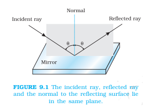
Spherical-Mirror Terms
- Pole (): The geometric centre of a spherical mirror.
- Centre of curvature (): The centre of the sphere of which the mirror is a part; the radius from to the surface gives the normal at the point of incidence.
- Principal axis: The straight line joining the pole and centre of curvature of a spherical mirror.
- Spherical lens: Its geometric centre is the optical centre; its principal axis joins the optical centre to its principal focus.
Cartesian Sign Convention
Rules for Measuring Distances and Heights
- Origin: Measure distances from the pole of a mirror or the optical centre of a lens.
- Distances: Along the direction of incident light is positive; opposite to it is negative.
- Heights: Above the principal axis is positive; below it is negative.
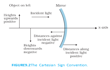
Principal Focus and Focal Length
Focus of a Spherical Mirror
- Paraxial rays: Rays close to the pole and making small angles with the principal axis are called paraxial rays.
- Concave mirror: Parallel paraxial rays reflect and converge at the principal focus .
- Convex mirror: Reflected parallel paraxial rays diverge and appear to come from the principal focus .
- Focal plane: For a parallel paraxial beam inclined to the principal axis, the reflected rays converge or appear to diverge from a point in the plane through perpendicular to the principal axis.
- Focal length (): The distance between the pole and principal focus .
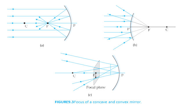
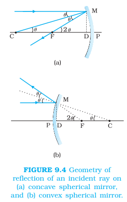
Relation Between Focal Length and Radius of Curvature
- Geometry: A ray parallel to the principal axis strikes the mirror at ; is normal to the surface. For paraxial rays, small-angle approximations apply.
- Approximation: For small , and .
- Result: The geometry gives . For paraxial rays, is close to , so and .
For paraxial rays, the focal length is half the radius of curvature.
Quick recap
- Visible light has wavelengths of about to ; use in vacuum.
- The speed of light in vacuum is the highest speed attainable in nature.
- A ray models light's straight-line path; a bundle of rays is a beam.
- Reflection obeys equal angles of incidence and reflection, with the incident ray, reflected ray and normal in one plane.
- For a spherical mirror, the normal is along the radius; the principal axis joins the pole and centre of curvature.
- Cartesian signs: incident-light direction and upward heights are positive; opposite distances and downward heights are negative.
- For paraxial rays, concave mirrors converge parallel rays and convex mirrors make them appear to diverge from the focus; .
The Mirror Equation
Images and Principal Rays
Image — An image is the point-to-point correspondence with an object formed by reflection and/or refraction.
| Point | Real image | Virtual image |
|---|---|---|
| Ray behaviour | Reflected rays actually converge at the image point. | Rays do not actually meet; they appear to diverge from the point when extended backwards. |
Useful Rays for Spherical Mirrors
- Parallel ray: A ray parallel to the principal axis reflects through the focus.
- Centre-of-curvature ray: A ray through the centre of curvature of a concave mirror, or directed towards it for a convex mirror, retraces its path.
- Focal ray: A ray through the focus of a concave mirror, or directed towards the focus of a convex mirror, reflects parallel to the principal axis.
- Pole ray: A ray incident at the pole reflects according to the laws of reflection.
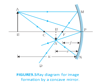
How an Image Point Is Formed
- Many rays: Every point on an object emits rays in many directions; a ray diagram shows only selected rays for convenience.
- Image point: For a real image, all reflected rays from an object point pass through its image point; for a virtual image, they appear to come from that point.
Deriving the Mirror Equation
Mirror equation — The mirror equation relates object distance , image distance and focal length for a spherical mirror.
Derivation Using Similar Triangles
- For paraxial rays, the relevant right-angled triangles give two expressions for the same ratio of image height to object height.
- Equate the ratios and use the signed-distance relation between the points.
- For the real, inverted image setup, the sign convention gives , and .
- Rearranging gives the mirror equation; with the proper sign convention, it applies to concave and convex mirrors and to real and virtual images.
Use with signed values of , and .
Sign Convention in the Derivation
- Positive direction: The direction in which incident light travels is taken as positive.
- Distances in the example: The image, focus and object lie opposite to the incident-light direction from the pole, so , and .
- General use: Apply the sign convention consistently; the equation is valid for spherical mirrors, whether the image is real or virtual.
Linear Magnification
Linear magnification — Linear magnification is the ratio of image height to object height .
Heights and distances take signs according to the accepted sign convention.
Using Magnification
- Height ratio: Similar triangles at the pole give after applying the sign convention.
- Sign meaning: The signs of and indicate the image and object orientations under the accepted convention.
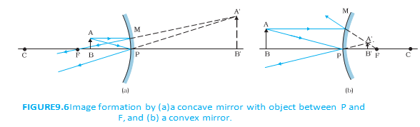
State the mirror equation and its symbols.
Write the linear magnification formula for a spherical mirror.
Quick recap
- A real image forms where reflected rays actually meet; a virtual image appears to form where rays diverge when extended backwards.
- Four useful mirror rays are the parallel, centre-of-curvature, focal and pole rays.
- The mirror equation is .
- Use the sign convention consistently for object distance, image distance and focal length.
- Linear magnification is .
- Both formulas apply to concave and convex mirrors and to real and virtual images.
Examples Based on The Mirror Equation
Reducing a Mirror’s Reflecting Area
- Image formation: Every point on an object can form its image through the reflected rays.
- Reduced reflecting area: Covering part of a mirror still produces the whole image, but with reduced intensity.
Image of an Object Along the Principal Axis
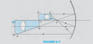
Why the image is distorted
- Different object points: Points along the principal axis are at different distances from the mirror, so their images form at different positions and have different magnifications.
- Transverse part: The part lying in a plane perpendicular to the principal axis is imaged in that plane; in the example, its image size equals its object size.
- Position matters: The distortion depends on where the object lies relative to the mirror, because the distances and magnifications of its parts change.
Finding Image Position and Magnification
Use the Cartesian sign convention for object distance , image distance and focal length .
For a spherical mirror, is its radius of curvature. The sign of magnification indicates orientation.
| Object distance | Image distance | Magnification | Image nature |
|---|---|---|---|
| Real, inverted and magnified; image is in front of the mirror. | |||
| Virtual, erect and magnified; image is behind the mirror. |
Sign and nature
- Focal length: For radius , a concave mirror has .
- Magnification: Negative means an inverted image; positive means an erect image. A virtual mirror image is behind the mirror.
Apparent Speed of an Image in a Convex Mirror
Rearrange the mirror equation to calculate the image position.
Calculate the change in image distance over the time interval.
| Jogger’s distance during interval | Image speed |
|---|---|
Key observation
- Non-uniform motion: Although the jogger’s speed is constant, the image’s apparent speed increases as the jogger approaches the mirror.
- Everyday example: The effect can be noticed in a stationary car or bus when a vehicle behind approaches at constant speed.
What happens to an image if half a mirror is covered?
For a concave mirror, what are the image position and nature when and ?
Why does the image of an object extending along the principal axis become distorted?
Quick recap
- Covering part of a mirror reduces image intensity, not the portion of the object imaged.
- An object extending along the principal axis can be distorted because its parts have different magnifications.
- Use and with the Cartesian sign convention.
- A concave mirror has negative focal length; a convex mirror has positive focal length.
- A jogger’s image in a convex mirror appears to move faster as the jogger approaches.
Refraction
Refraction of Light
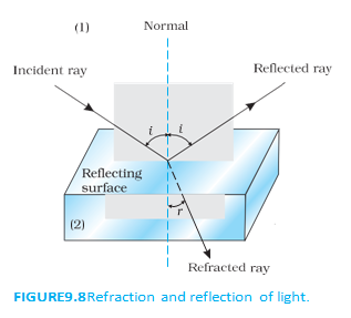
Laws of Refraction and Snell’s Law
is the refractive index of medium with respect to medium .
What the Refractive Index Tells Us
- Depends on: The refractive index depends on the pair of media and the wavelength of light, but not on the angle of incidence.
- If : Then ; the ray bends towards the normal, and medium is optically denser than medium .
- If : Then ; the ray bends away from the normal, as light passes from an optically denser medium to a rarer one.
| Point | Optical density | Mass density |
|---|---|---|
| Meaning | Related to the relative speeds of light in two media; refractive index is their speed ratio. | Mass per unit volume. |
| Comparison | A medium may be optically denser even if its mass density is lower. | Does not determine optical density. |
| Example | Turpentine is optically denser than water. | Turpentine has lower mass density than water. |
Do not use mass density to decide optical density; optical density concerns light’s relative speed in media, not mass per unit volume.
Refractive Indices Between Multiple Media
Here, means the refractive index of medium with respect to medium .
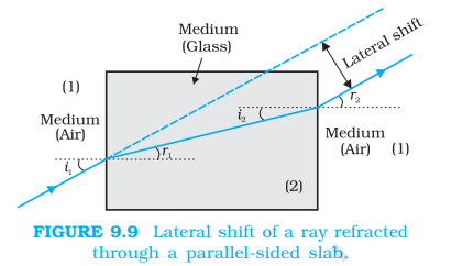
Refraction Through a Parallel-Sided Glass Slab
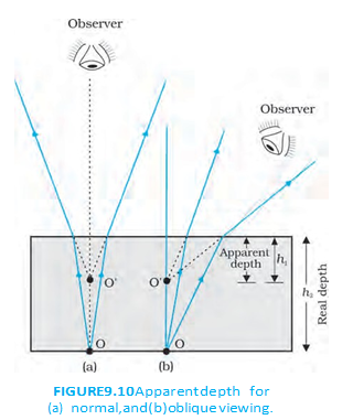
Apparent Depth
is the apparent depth, is the real depth, and is the refractive index of the medium relative to the viewing medium.
State Snell’s law and explain the meaning of .
What happens to a ray passing through a parallel-sided glass slab?
Quick recap
- Refraction is the change in direction of an oblique ray at a boundary between transparent media.
- The incident ray, refracted ray, and normal lie in one plane; Snell’s law is .
- For , the ray bends towards the normal; for , it bends away.
- Refractive indices reverse reciprocally and combine multiplicatively across three media.
- A parallel-sided slab produces a parallel emergent ray with lateral shift.
- For near-normal viewing, apparent depth is real depth divided by refractive index.
Total Internal Reflection
Internal Reflection and Total Internal Reflection
Internal reflection — When light travels from an optically denser medium to a rarer medium, some light is reflected back into the denser medium while the rest is refracted into the rarer medium.
How total internal reflection occurs
- Refraction: From a denser to a rarer medium, the refracted ray bends away from the normal; hence .
- Increasing incidence angle: The refraction angle increases until the refracted ray grazes the interface, with .
- Beyond the critical angle: Refraction is no longer possible, and the light is totally reflected back into the denser medium.
- Intensity: In ordinary reflection, some light is transmitted, so the reflected ray is less intense than the incident ray. In total internal reflection, no light is transmitted.
Critical angle — The angle of incidence in the denser medium for which the refracted ray in the rarer medium makes an angle of with the normal.
Conditions for total internal reflection
- Direction: Light must travel from an optically denser medium to an optically rarer medium.
- Incidence angle: The angle of incidence must be greater than the critical angle: .
- At the critical angle: and ; the refracted ray grazes the interface.
- Below the critical angle: For , light is partly reflected and partly refracted.
For light travelling from medium (denser) to medium (rarer), is the refractive index of medium relative to medium .
The refractive index of medium relative to medium is the reciprocal of .
| Substance | Refractive index | Critical angle |
|---|---|---|
| Water | ||
| Crown glass | ||
| Dense flint glass | ||
| Diamond |
Applications of Total Internal Reflection
Prisms
- Uses: Prisms use total internal reflection to turn light through or , and can invert an image without changing its size.
- Condition: For the and turning arrangements, the prism material must have .
- Examples: Crown glass and dense flint glass satisfy this critical-angle condition.
Optical fibres
- Structure: Each fibre has a core surrounded by cladding; the core has a higher refractive index than the cladding.
- Working: Light entering at a suitable angle undergoes repeated total internal reflections at the core–cladding boundary and travels along the fibre.
- Signal transmission: Fibres carry audio, video and other optical signals over long distances, with little loss of light intensity.
- Electrical signals: Suitable transducers convert electrical signals into light for transmission through fibres and convert received light signals back into electrical signals.
- Flexibility: Fibres are designed so reflections continue even when the fibre bends.
- Uses: Fibre bundles act as light pipes for examining internal organs such as the oesophagus, stomach and intestines; decorative fibre lamps are another example.
- Material quality: Very low light absorption is essential. Specially prepared silica glass fibres can transmit more than of the light over .
State the two conditions required for total internal reflection.
How does an optical fibre transmit light?
Quick recap
- Total internal reflection occurs only from a denser to a rarer medium when .
- At the critical angle, and .
- In ordinary reflection, some light is transmitted and the reflected ray is less intense; in total internal reflection, no light is transmitted.
- Prisms use total internal reflection to turn light through or and to invert images without changing their size.
- Optical fibres guide light through repeated total internal reflection in a higher-index core surrounded by lower-index cladding.
Refraction at Spherical Surfaces and by Lenses
Spherical Refracting Surface
Thin lens — A transparent optical medium bounded by two surfaces, at least one of which is spherical.
From Spherical Surfaces to Lenses
- Two-surface application: Applying the spherical-surface relation successively at a lens’s two surfaces leads to the lens-maker’s formula and the lens formula.
Refraction Relation
Deriving the Spherical-Surface Relation
- Use paraxial geometry to express the angles of incidence and refraction in terms of distances.
- Apply Snell’s law and the small-angle approximation.
- Substitute the angle expressions, then apply the Cartesian sign convention.
Relates object distance, image distance, refractive indices, and radius of curvature.
Symbols and Sign Convention
- Indices: and are the refractive indices of the incident and refracting media, respectively.
- Distances: is object distance, is image distance, and is radius of curvature.
- Signs: With the Cartesian convention, distances are measured from the surface; the positive direction is the direction of incident light.
- Typical signs: A real object on the incident side has ; an image in the direction of light travel has .
Example: Air to Glass
- Given: , , , and .
- Substitution: , giving .
- Image position: The image forms from the surface in the direction of incident light.
Do not substitute unsigned distances: assign Cartesian signs to , , and before using the formula.
State the relation for refraction at a spherical surface and identify its quantities.
Quick recap
- A spherical surface refracts light at the boundary between two transparent media; its normal passes through the centre of curvature.
- The derivation assumes a small aperture and paraxial rays, allowing small-angle approximations.
- Use with signed distances.
- A thin lens has two bounding surfaces, at least one of them spherical.
- Applying the spherical-surface relation at both lens surfaces gives the lens-maker’s formula and the lens formula.
- For the air-to-glass example, the image distance is .
Refraction by a lens
How a Lens Forms an Image
- Two refractions: A lens forms an image by refraction at each of its two surfaces.
- Intermediate image: The first surface forms an image that acts as the object for the second surface.
- Thin-lens approximation: The two surfaces are close together, so distances can be measured from the lens’s optical centre.
Lens Maker’s Formula
For a thin lens surrounded by a medium, using signed radii of curvature:
Thin Lens Formula and Foci
Use signed object distance , image distance and focal length .
Principal Ray Rules
- Parallel ray: A ray parallel to the principal axis refracts through the second focus of a convex lens, or appears to diverge from the first focus of a concave lens.
- Optical-centre ray: A ray through the optical centre emerges without deviation.
- Focal ray: A ray through the first focus of a convex lens, or directed towards the second focus of a concave lens, emerges parallel to the principal axis.
Magnification by a Lens
Use signed heights and distances.
Lens in a Matching Medium
State the lens maker’s formula and define its refractive-index term.
Why does a lens disappear when immersed in a liquid of the same refractive index?
Quick recap
- A lens forms its final image through refraction at two surfaces.
- The lens maker’s formula connects focal length with relative refractive index and signed surface radii.
- A concave lens has negative focal length under the stated sign convention.
- The thin lens formula is and works for both lens types and real or virtual images.
- The first focus is on the original source side; the second focus is on the opposite side.
- Use any two principal rays to locate an image; magnification is .
- If lens and medium have equal refractive indices, the lens has infinite focal length.
Power of Lens
Meaning and Formula for Lens Power
Use focal length in metres. The SI unit is the dioptre, where .
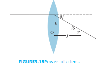
| Lens type | Action | Power and focal length |
|---|---|---|
| Convex | Converges light | , |
| Concave | Diverges light | , |
Power examples
- Prescription: A lens of is convex and has .
- Prescription: A lens of is concave and has .
Lens Formula in a Surrounding Medium
For a lens of refractive index in a medium of refractive index , changing the medium changes the focal length. and are the signed radii of curvature.
Lens-power and lens-maker examples
- For a glass lens with , calculate power using focal length in metres.
- For the double-convex lens, use , , and ; take air's refractive index as .
- For the same lens, compare its lens-maker formula in air (, , ) and water (, ).
Combination of Thin Lenses in Contact
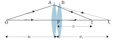
The intermediate image distance cancels when the two lens equations are added.
For an equivalent single lens, is the equivalent focal length and , are the individual focal lengths.
Equivalent power is the algebraic sum of the individual lens powers; convex and concave lens powers retain their signs.
The total magnification is the product of the magnifications of the individual lenses.
Why combine lenses?
- Design: Combinations can provide a desired convergence or divergence and magnification.
- Image quality: A lens system can improve image sharpness.
- Applications: Lens combinations are used in cameras, microscopes, telescopes and other optical instruments.
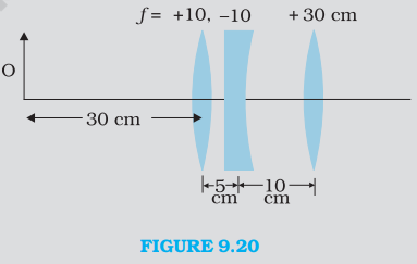
Finding the final image through successive lenses
- For the first lens, use and .
- The second lens is to the right of the first, so the intermediate image is to its right and is a virtual object for it.
- The third lens receives parallel rays, so its image is at its focal point.
- The final image is formed to the right of the third lens.
Do not add focal lengths directly for lenses in contact: add their reciprocals, or equivalently add their signed powers. Apply the sign convention separately at each lens.
What is the SI unit of lens power, and how is it related to focal length?
State the equivalent power of thin lenses in contact.
Quick recap
- Lens power measures convergence or divergence and is with in metres.
- Convex lenses have positive power; concave lenses have negative power.
- One dioptre equals .
- For lenses in contact, add reciprocal focal lengths or signed powers.
- The total magnification of a combination is the product of the individual magnifications.
- For successive lenses, each image becomes the next lens's object; check its position and sign.
Refraction Through a Prism
Prism Geometry and Deviation
Angle of deviation — The angle between the direction of the incident ray and the emergent ray after refraction through a prism.
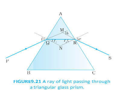
Angle relationships
- Notation: is the angle of incidence at the first face; and are the internal refraction angles at the first and second faces; is the angle of emergence.
- Prism angle: If is the angle between the prism’s refracting faces, geometry gives .
- Total deviation: The deviations at the two faces add: .
- Dependence: The deviation changes with the incidence angle .
Minimum Deviation and Refractive Index
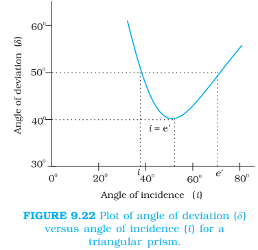
Minimum deviation
- Minimum condition: At minimum deviation , the path through the prism is symmetric: and .
- Internal ray: At this condition, the refracted ray inside the prism is parallel to its base.
- Equal refraction angles: From , each internal angle is .
- Incidence angle: Using , the minimum-deviation incidence angle is .
- Graph symmetry: A given deviation generally corresponds to two incidence angles, except at the minimum; interchanging and leaves unchanged.
Use the measured prism angle and minimum deviation to determine the refractive index of the prism relative to its surrounding medium.
Thin Prism
- Thin prism: A prism with a small angle has a small minimum deviation, so it bends light only slightly.
- Small-angle result: For a thin prism, using the small-angle approximation gives ; angles are in radians.
For small prism angles, with angles measured in radians.
State the conditions at minimum deviation through a prism.
Write the refractive-index formula for a prism at minimum deviation.
Quick recap
- The internal angles satisfy .
- The prism deviation is .
- At minimum deviation, and .
- The minimum-deviation formula gives the prism’s refractive index from and .
- For a thin prism, with angles in radians.
Optical Instruments
Optical instruments
- Principle: Optical instruments use reflection and refraction by mirrors, lenses and prisms.
- Examples: Periscopes, kaleidoscopes, binoculars, telescopes and microscopes; the human eye is also an important optical device.
- Microscopes: They help view small objects by producing magnified images.
Simple Microscope
Simple microscope — A simple microscope is a short-focal-length converging lens that produces an enlarged, erect, virtual image.
Image formation and magnification
- Placement: Hold the lens close to the object, with the object inside its focal length; place the eye close to the lens on the other side.
- Image: The image is virtual, erect and magnified. It may be formed at the near point or at infinity.
- Near point: The least distance of distinct vision is approximately . Viewing an image there gives greater magnification but may strain the eye.
- Relaxed viewing: An image at infinity is more comfortable to view and is usually assumed for optical instruments.
- Object at focus: When the object is at the focal point, the image is at infinity.
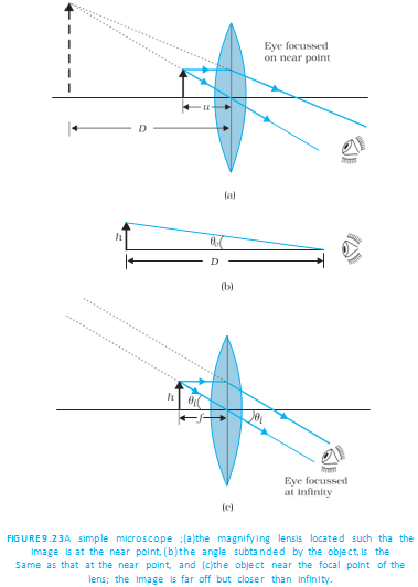
Using magnitudes, the image at the near point has magnification .
Angular magnification
- Unaided viewing: For an object of height at the near point, the angle subtended is approximately .
- With the lens at focus: For the final image at infinity, the angle subtended is approximately .
- Definition: Angular magnification is the ratio of the angle subtended through the instrument to the angle subtended by the unaided object at the near point.
For a relaxed eye, the simple microscope’s angular magnification is:
| Point of comparison | Image at near point | Image at infinity |
|---|---|---|
| Magnification | ||
| Viewing comfort | May strain the eye | More comfortable for a relaxed eye |
Simple microscope: practical limit
- Maximum magnification: A simple microscope has a limited maximum magnification of about for realistic focal lengths.
- Reason for compound microscopes: Much larger magnifications require two lenses that compound their effects.
- Example: For and near-point magnification , ; use a convex lens of focal length .
Compound Microscope
Compound microscope — A compound microscope uses an objective and an eyepiece to produce a much more magnified image than a simple microscope.
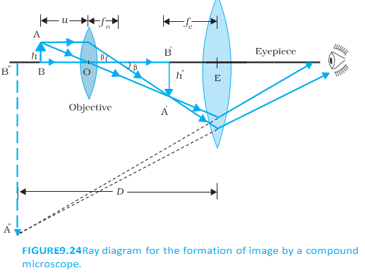
How the lenses work
- Objective: The lens nearest the object forms the first image, which is real, inverted and magnified.
- Eyepiece: The first image acts as its object; the eyepiece works like a simple microscope and forms the final enlarged, virtual image.
- Final image: It is inverted relative to the original object. The first image lies at or near the eyepiece’s focal plane for viewing at infinity or near the near point.
- Tube length: is the distance between the objective’s second focal point and the eyepiece’s first focal point.
The objective’s linear magnification is approximately the tube length divided by its focal length.
| Final image position | Eyepiece magnification |
|---|---|
| At the near point | |
| At infinity |
The total magnification is the product of the objective’s linear magnification and the eyepiece’s angular magnification.
Design and example
- Large magnification: Use short focal lengths for both lenses and a large tube length.
- Practical limit: Lens focal lengths are difficult to make much shorter than about ; a large tube length also requires large lenses.
- Example: For , , and , .
- Image quality: Illumination affects visibility. Modern microscopes use multi-component objective and eyepiece lenses to reduce optical aberrations.
State the magnification of a simple microscope when the final image is at the near point and at infinity.
Describe the image formation in a compound microscope and give its magnification when the final image is at infinity.
Quick recap
- A simple microscope is a short-focal-length converging lens that forms an erect, virtual, magnified image.
- Simple microscope magnification is at the near point and at infinity.
- For , near-point magnification requires a convex lens with .
- A simple microscope’s realistic maximum magnification is about ; compound microscopes provide much larger magnification.
- The compound microscope’s objective forms a real, inverted, enlarged first image, which the eyepiece magnifies.
- For a final image at infinity, compound microscope magnification is ; short lens focal lengths and a long tube length increase it.
Telescope, Summary and Points to Ponder
Telescope: Principle and Magnifying Power
Telescope — An optical instrument that increases the angular size of distant objects.
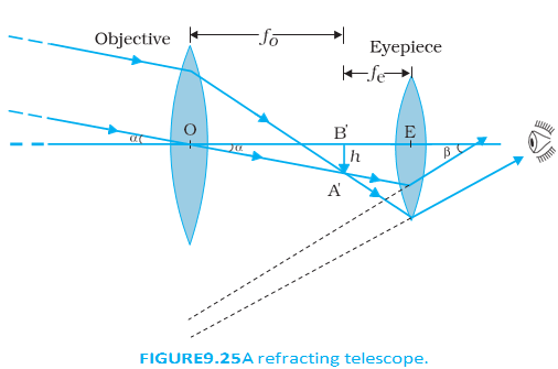
Refracting Telescope
- Objective: Has a long focal length and an aperture much larger than the eyepiece’s; it collects light from a distant object and forms a real image at its second focal point.
- Eyepiece: Has a short focal length and magnifies the objective’s image, producing a final inverted image.
- Normal adjustment: The objective’s image lies at the eyepiece’s focal plane, so the final image is at infinity and the tube length is .
- Terrestrial telescope: Uses an additional pair of inverting lenses to make the final image erect.
Magnifying power is the ratio of the angle subtended by the final image at the eye to the angle subtended by the object.
Example
- Calculation: If and , then .
- Apparent separation: Stars separated by appear separated by through this telescope.
Astronomical and Reflecting Telescopes
What Makes an Astronomical Telescope Powerful?
- Light-gathering power: Depends on the objective’s area; a larger objective collects more light and reveals fainter objects.
- Resolving power: The ability to distinguish two objects that appear nearly in the same direction; it also improves with objective diameter.
- Design goal: Astronomical telescopes therefore use objectives with large diameters.
| Point | Refracting telescope | Reflecting telescope |
|---|---|---|
| Objective | Lens | Concave mirror |
| Main challenge | Large lenses are heavy, hard to support at the edges, and costly to make free of chromatic aberration and distortion. | The observer or cage can obstruct some light if placed in the focused beam. |
| Advantages | Can be used for terrestrial and astronomical observations. | Mirrors have no chromatic aberration, weigh less than equivalent lenses, and can be supported across the back. |
Telescope Examples and Cassegrain Design
- Large refracting objective: The largest lens objective cited is inches (about ), at Yerkes Observatory, Wisconsin, USA.
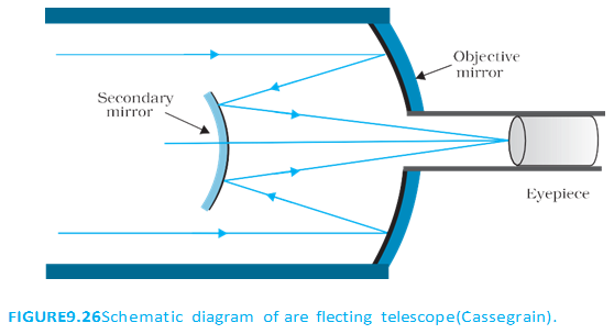
- Palomar telescope: The -inch (about ) reflecting telescope places the observer in a small cage near the mirror’s focal point.
- Cassegrain telescope: A convex secondary mirror redirects light through a hole in the primary mirror; this gives a large focal length in a short tube.
- India: The Cassegrain reflecting telescope at Kavalur, Tamil Nadu, is operated by the Indian Institute of Astrophysics, Bangalore.
- Keck telescopes: The pair in Hawaii, USA, have reflectors in diameter.
Chapter Summary: Core Laws and Formulas
Reflection, Refraction and Total Internal Reflection
- Coplanarity: The incident ray, reflected ray, refracted ray and normal lie in the same plane at the point of incidence.
- Reflection: The angle of incidence equals the angle of reflection.
- Refraction: Snell’s law relates the angles and refractive index; for relative refractive index , .
- Critical angle: For light travelling from a denser to a rarer medium, it is the angle of incidence that gives a refraction angle of .
- Total internal reflection: Occurs when incidence from the denser medium exceeds the critical angle; examples include diamond, totally reflecting prisms and mirages.
- Optical fibre: A glass core coated with a lower-refractive-index material guides light by repeated total internal reflection, even when bent.
Here is the angle of incidence, the angle of reflection and the angle of refraction.
Cartesian Sign Convention
- Distances: Measured from the mirror’s pole or lens’s optical centre along the principal axis; the incident-light direction is positive and the opposite direction is negative.
- Heights: Measured perpendicular to the principal axis; upward is positive and downward is negative.
Here and are object and image distances; is approximately half the radius of curvature . A concave mirror has negative and a convex mirror has positive .
For a prism of angle and refractive index in a medium of refractive index , is the angle of minimum deviation and is the relative refractive index.
For refraction from medium to medium , and are object and image distances, and is the surface’s radius of curvature.
For a lens in a surrounding medium of refractive index , is the lens refractive index; and are its surface radii. A converging lens has positive and a diverging lens has negative .
Lens Power and Combinations
- Power: , with measured in metres; the SI unit is the dioptre, where .
- Lenses in contact: Their reciprocal focal lengths and powers add to give the combination’s effective values.
For several thin lenses in contact, and refer to the equivalent combination.
Dispersion — The splitting of light into its constituent colours.
Microscopes and Telescope: Magnifying Power
is the least distance of distinct vision and is the convex lens’s focal length. Use the first expression for the final image at the near point and the second when it is at infinity.
is the objective magnification, and are objective and eyepiece focal lengths, and is the distance between their focal points.
The angular magnifying power is the ratio of the angle subtended by the image at the eye to that subtended by the object.
Points to Ponder
How Images Form and Are Seen
- Optical laws: The laws of reflection and refraction apply at the point of incidence for all surfaces and pairs of media.
- Image in air: A real image exists where rays from each object point converge, even without a screen; the screen only scatters some rays into the observer’s eyes.
- Regular surfaces: Image formation requires regular reflection or refraction so rays from each object point meet at a corresponding image point.
- Irregular surfaces: Scattered rays do not form a clear image; for example, a book page does not show your image.
Colour and Dispersion
- Thick lenses: Dispersion can produce coloured images.
- Object colours: The colours we perceive depend on the constituent colours of the light illuminating an object; monochromatic light can make objects appear different from how they appear in white light.
Why a Simple Microscope Magnifies
- Angular size: A simple microscope’s object and image have equal angular size, but magnification is possible because the object can be brought closer to the eye than .
- Comparison: Without the microscope, the small object must be viewed from about and subtends a much smaller angle; the microscope forms a visible image at that distance.
Why do reflecting telescopes use a concave mirror instead of a large objective lens?
What is total internal reflection, and what is its condition?
State the magnifying-power formula for a telescope in normal adjustment.
Quick recap
- A telescope magnifies angular size; its objective has a long focal length and an aperture much larger than the eyepiece’s.
- The objective forms a real image at its second focal point; in normal adjustment, magnifying power is and tube length is .
- Larger objective diameter improves light gathering and resolution; reflecting telescopes avoid chromatic aberration.
- Reflection, refraction, mirror, lens, prism and optical-instrument relations depend on the stated sign conventions and definitions.
- Total internal reflection occurs for incidence beyond the critical angle when light travels from a denser to a rarer medium.
- A real image can exist without a screen, while a simple microscope magnifies by allowing the object to subtend a larger angle.
Physics — ALL CHAPTERS
1
Electric Charges And Fields
2
Electrostatic Potential And Capacitance
3
Current Electricity
4
Moving Charges And Magnetism
5
Magnetism And Matter
6
Electromagnetic Induction
7
Alternating Current
8
Electromagnetic Waves
1
Ray Optics And Optical Instruments
2
Wave Optics
3
Dual Nature Of Radiation And Matter
4
Atoms
5
Nuclei
6
Semiconductor Electronics: Materials, Devices And Simple Circuits