Class 12 PCB . Physics . Physics Part II . Wave Optics
Chapter 2: Wave Optics
Ch 2
Physics
Class 12 PCB
Introduction
Corpuscular and Wave Models of Light
- Corpuscular model: Descartes proposed it in 1637; Newton later developed it. It treated light as particles and explained reflection and refraction.
- Wave model: Huygens proposed it in 1678, describing light as a wave that can explain reflection and refraction.
- Different predictions: The models differed on how light’s speed changes when it bends towards the normal at a boundary.
Evidence for the Wave Nature of Light
- Young’s experiment: In 1801, Young’s interference experiment established that light exhibits wave behaviour.
- Interference and diffraction: Experiments over the following decades showed that these phenomena could be explained by the wave model.
- Speed in water: Foucault’s 1850 experiment found that light travels more slowly in water than in air, as predicted by the wave model.
Geometrical Optics
- Approximation: Geometrical optics neglects the finite wavelength of light, treating it as tending to zero.
- Ray: A ray represents the path of energy propagation in this limit.
- Application: Since visible-light wavelengths are very small compared with typical mirrors and lenses, light can often be treated as travelling in straight lines.
Maxwell’s Electromagnetic Theory
- Electromagnetic waves: Maxwell’s equations led to a wave equation predicting electromagnetic waves.
- Light as an electromagnetic wave: The predicted speed of electromagnetic waves in free space was close to the measured speed of light.
- Propagation in vacuum: Changing electric and magnetic fields sustain one another, allowing light waves to travel without a material medium.
Topics in This Chapter
- Huygens’ principle: Use wavefronts to understand the laws of reflection and refraction.
- Interference: Study superposition and the interference patterns produced by light waves.
- Diffraction: Examine how light spreads around obstacles and through narrow openings.
- Polarisation: Explore the transverse nature of light and how its vibrations can be restricted.
Quick recap
- Descartes’ corpuscular model and Huygens’ wave model made opposite predictions about light’s speed when it bends towards the normal.
- Foucault’s 1850 result that light is slower in water than in air supported the wave prediction.
- Young’s 1801 interference experiment and later diffraction observations established strong evidence for light’s wave nature.
- Geometrical optics neglects wavelength; a ray represents energy propagation as wavelength tends to zero.
- Maxwell identified light as an electromagnetic wave that propagates through vacuum.
- Interference uses superposition, diffraction uses the Huygens–Fresnel principle, and polarisation reflects light’s transverse nature.
Huygens Principle
Wavefronts and Their Types
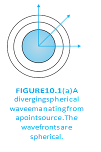
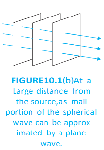
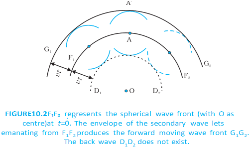
Huygens’ Principle
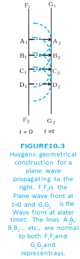
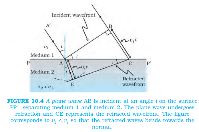
Refraction of a Plane Wave
From the geometry of the construction:
Dividing the angle relations gives:
Refractive Index and Snell’s Law
- Refractive index: For light in a medium, refractive index is the speed of light in vacuum divided by its speed in that medium.
- Wave-theory prediction: If light bends towards the normal, its speed in the second medium is lower. This prediction is opposite to the corpuscular model’s prediction; experiments support wave theory.
- Snell’s law: The speed relation expressed using refractive indices gives the law of refraction.
For media 1 and 2, where is the speed of light in vacuum:
For light passing between two media:
Wavelength and Frequency During Refraction
Since frequency equals wave speed divided by wavelength:
Frequency does not change during refraction: speed and wavelength change together, while frequency stays constant.
State Huygens’ principle.
State Snell’s law and the relation between the angles and wave speeds.
What happens to light’s speed, wavelength and frequency when it enters a slower medium?
Quick recap
- A wavefront is a surface of constant phase; wave energy travels perpendicular to it.
- Point sources produce spherical wavefronts; a small distant region can be treated as plane.
- Secondary wavelets spread at wave speed, and their forward common envelope gives the later wavefront.
- Refraction involves a speed change across a boundary; direction changes only when the incidence is not normal.
- Refraction obeys and .
- In a slower medium, light’s speed and wavelength decrease but its frequency remains constant.
Refraction at a rarer medium
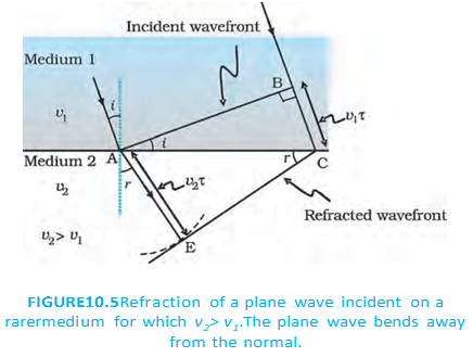
Refraction into a Rarer Medium
For light travelling from a denser medium with refractive index into a rarer medium with refractive index :
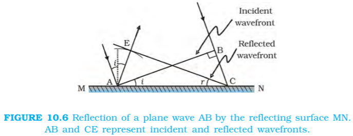
Reflection of a Plane Wave
The incident and reflected angles are measured from the normal.
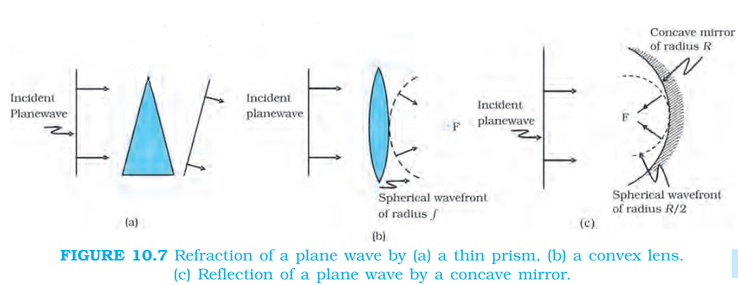
Wavefronts in Optical Devices
- Equal travel time: For an object point and its corresponding image point, the travel time is the same along every ray.
- Convex lens example: A central ray travels a shorter path but moves more slowly in glass; its travel time matches that of rays near the lens edge.
Frequency and Intensity of Light
Intensity is proportional to the square of the wave amplitude.
Why do reflected and refracted light retain the incident frequency?
Does lower wave speed necessarily mean lower light energy?
What determines light intensity in the wave and photon pictures?
Quick recap
- Light entering a rarer medium bends away from the normal and obeys Snell’s law.
- At the critical angle, refraction is at ; above it, total internal reflection occurs.
- Wavefront construction gives the law of reflection, .
- Prisms, lenses and mirrors shape wavefronts by delaying or redirecting portions of them.
- For an object-image pair, travel time is the same along every ray.
- Frequency is unchanged at a boundary; wave intensity is proportional to amplitude squared, while photon intensity depends on photon rate per unit area.
Coherent and Incoherent Addition of Waves
Superposition and Coherent Sources
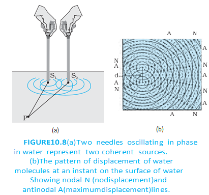
Constructive and Destructive Interference
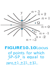
Interference from Two In-Phase Sources
- Constructive interference: Waves arrive in phase and reinforce; for equal-amplitude waves the resultant intensity is .
- Destructive interference: Waves arrive out of phase by an odd multiple of and cancel; for equal amplitudes the intensity is zero.
- Equal-path example: At a point equidistant from the sources, in-phase waves arrive in phase, giving maximum intensity.
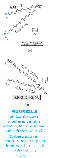
- Path difference: A difference of corresponds to phase difference , so the waves again arrive in phase.
- Amplitude assumption: For points far from the sources compared with their separation, the two wave amplitudes are approximately equal.
The path difference is an integer multiple of the wavelength.
The path difference is an odd half-wavelength.
Resultant Displacement and Intensity
Two Equal-Amplitude Waves
- Phase difference: At a general point, the waves can differ in phase by .
- Amplitude: The resultant amplitude is ; intensity depends on the square of the amplitude.
- Maximum intensity: For , the waves reinforce and .
- Zero intensity: For , the waves cancel.
For waves with displacements and :
is the intensity due to either one of the equal-amplitude sources.
Path Difference and Phase Difference
- Relation: A path difference of produces phase difference .
- Maxima: corresponds to phase difference .
- Minima: corresponds to phase difference .
Incoherent Addition of Waves
Time-Averaged Intensity
- Incoherent sources: Their phase difference changes rapidly with time, so maxima and minima shift rapidly.
- Observed result: The rapidly changing pattern is seen as a time-averaged intensity; the individual intensities add.
- Example: Two separate light sources illuminating a wall are incoherent.
For sources each producing intensity , the average intensity is the sum of their intensities.
Quick recap
- Superposition: Resultant displacement is the vector sum of the individual wave displacements.
- Coherence: A constant phase difference gives a stable interference pattern.
- Constructive interference: Path difference gives maximum intensity for equal sources.
- Destructive interference: Path difference gives zero intensity for equal sources.
- Resultant displacement: ; the amplitude is .
- Coherent-wave intensity: .
- Incoherent sources: Rapidly varying phase difference gives average intensity for two equal sources.
Interference of Light Waves and Young’s Experiment
Interference and Coherence
- Coherent sources: They have the same frequency and maintain a constant phase difference, producing a stable interference pattern.
- Constructive interference: For in-phase sources, a path difference of an integer multiple of the wavelength gives maximum intensity.
- Destructive interference: A path difference of a half-integer multiple of the wavelength gives minimum intensity; for equal amplitudes, it is zero.
- Incoherent sources: Their phase difference changes randomly, so the intensities add and no stable fringes are observed.
Young’s Double-Slit Experiment
Path difference — The difference between the distances travelled by the two waves from their sources to a point on the screen.
Symbols and screen geometry
- is the separation between the two pinholes; is their distance from the screen.
- is the displacement of a fringe from the central point; is the wavelength of light.
- Path difference At displacement , the path difference is approximately .
Bright and Dark Fringes
Conditions and positions
- Bright fringe Constructive interference occurs when the path difference is an integer multiple of the wavelength: .
- Dark fringe Destructive interference occurs when the path difference is a half-integer multiple of the wavelength: .
- Order Here, is an integer; the central bright fringe corresponds to .
Use for constructive interference on the screen.
Use for destructive interference on the screen.
The equal spacing between successive bright fringes, or successive dark fringes.
Why do two independent sodium lamps not produce stable interference fringes?
How does Young obtain coherent sources in the double-slit experiment?
Quick recap
- Stable interference requires coherent sources with a fixed phase relationship.
- Independent ordinary sources are incoherent, so their intensities add without stable fringes.
- Young’s two nearby pinholes act as coherent sources when illuminated by the same original source.
- The path difference at screen displacement is approximately .
- Bright fringes occur at ; dark fringes occur at .
- Bright and dark fringes are equally spaced, with fringe width .
Diffraction
Diffraction — The spreading of waves around obstacles or through narrow openings into regions of geometrical shadow.
When diffraction matters
- All waves can diffract, including sound, light, water and matter waves.
- Visibility: Light’s wavelength is much smaller than most everyday obstacles, so its diffraction is usually hard to notice.
- Applications and effects: Diffraction limits the resolution of eyes and optical instruments; the colours seen on a CD arise from diffraction.
Diffraction at a Single Slit
Setup and wavefront idea
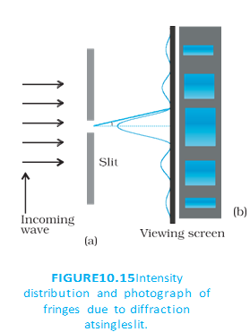
- Setup: A parallel monochromatic beam falls normally on a slit of width ; the diffracted light reaches a screen.
- Secondary sources: Treat each small part of the slit as a source of waves. They are initially in phase because the incoming wavefront is parallel to the slit.
- At an angle: For a screen point viewed at angle from the normal, waves from different parts of the slit travel different distances and acquire phase differences.
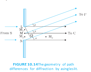
The path difference between waves from the two edges of the slit is:
Destructive cancellation gives zero intensity at the minima. For small angles, their positions are approximately:
There is a central maximum at zero angle; approximate positions of the weaker secondary maxima are:
Single-slit pattern
- Central bright region: The central maximum is broad and lies at .
- Side fringes: Dark minima and bright secondary maxima alternate on both sides.
- Intensity: Secondary maxima become progressively weaker farther from the centre.
| Point | Interference | Diffraction |
|---|---|---|
| Usual description | Often used when a small number of sources, such as two, combine. | Often used when contributions from many parts of a wavefront combine. |
| Physical basis | Superposition of waves. | Superposition of waves; there is no sharp fundamental physical distinction from interference. |
| Double-slit pattern | The two slits produce an interference pattern. | Each slit also produces a single-slit diffraction pattern; the observed pattern is their superposition. |
Wavelength and fringe width
- Wavelength dependence: Fringe positions depend on wavelength, so white light can produce coloured bands.
- Red and blue light: Red light has a longer wavelength than blue light, so its fringes are wider.
Energy in Diffraction and Interference
- Redistribution: Light energy shifts between regions: reduced intensity at dark fringes is balanced by increased intensity in bright regions.
- Conservation: Interference and diffraction redistribute energy; they do not create or destroy it.
State the condition for minima in single-slit diffraction.
Describe the single-slit diffraction pattern.
How does a double-slit pattern combine interference and diffraction?
Quick recap
- Diffraction is the spreading of waves around obstacles or through narrow openings.
- A single slit acts as many in-phase secondary sources whose waves combine at the screen.
- Single-slit minima occur approximately at for nonzero integer .
- The pattern has a broad central maximum and weaker secondary maxima on either side.
- A double-slit pattern combines single-slit diffraction with two-slit interference.
- Diffraction and interference redistribute light energy without changing the total.
Polarisation
Transverse and Polarised Waves
Transverse wave — A wave is transverse when its displacement is perpendicular to its direction of propagation.
Wave Description
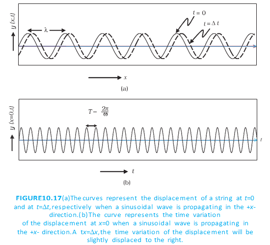
- String wave: If a string moves up and down while the wave travels along , displacement is along and is perpendicular to propagation.
- Wave equation: A sinusoidal wave travelling along is described by .
- Parameters: is amplitude, is angular frequency, is frequency, and is wavelength.
- Linear polarisation: A wave whose vibrations are restricted to one fixed direction is linearly polarised.
- Plane polarisation: A wave whose vibrations remain confined to a single plane is plane-polarised.
| Wave type | Vibration | Example |
|---|---|---|
| Y-polarised | Along | |
| Z-polarised | Along | |
| Unpolarised | Direction changes randomly, but remains perpendicular to propagation | Ordinary light |
Polarisation of Light
Polarisation — Polarisation is the restriction of a transverse wave’s vibrations to a particular direction or plane.
Light and Polaroids
- Light waves: Light is transverse; its electric field oscillates perpendicular to the direction of propagation.
- Polaroid structure: A polaroid contains long-chain molecules aligned in one direction.
- Selective absorption: Electric-field oscillations parallel to the aligned molecules are absorbed; the transmitted field oscillates perpendicular to them.
- Pass-axis: The direction of the transmitted electric-field oscillation is the polaroid’s pass-axis.
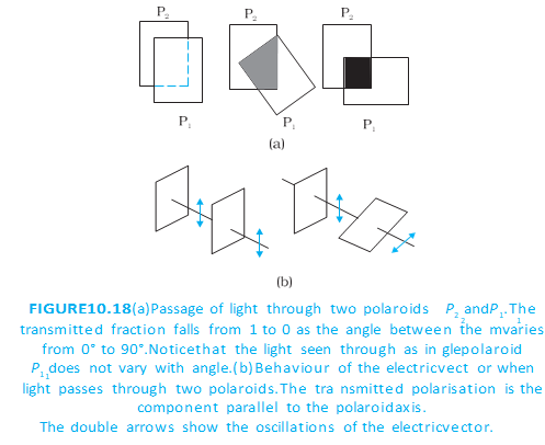
Transmission through Polaroids
- Unpolarised input: A polaroid transmits half the incident intensity and produces linearly polarised light.
- Rotation of one polaroid: Rotating it does not change the intensity transmitted from unpolarised light, because the input has no preferred vibration direction.
- Two polaroids: The first polarises the light; the second controls transmission according to the angle between their pass-axes.
- Crossed polaroids: Pass-axes at ideally block the polarised beam; parallel axes transmit the maximum intensity.
For polarised light incident on a second polaroid, transmitted intensity depends on the angle between the pass-axes.
Using Malus’ Law
- Symbols: is the intensity of polarised light incident on the second polaroid; is the angle between the pass-axes.
- Reason: The transmitted electric-field amplitude is proportional to ; intensity is proportional to amplitude squared.
- Parallel axes: At , .
- Crossed axes: At , ideally.
A Polaroid between Crossed Polaroids
- Setup: The first and final polaroids are crossed. A third polaroid has its pass-axis at angle to the first.
- After the middle polaroid: The intensity is , where is the intensity after the first polaroid.
- After the final polaroid: The angle between the middle and final axes is ; hence .
- Maximum transmission: The intensity is maximum at (or ), giving .
- Zero transmission: The final intensity is zero when the middle polaroid is parallel to either crossed outer polaroid.
Applications
- Intensity control: Polaroids vary transmitted light by changing the angle between their pass-axes.
- Uses: Polaroids are used in sunglasses, windowpanes, photographic cameras and 3D movie cameras.
Do not apply Malus’ law directly to unpolarised light: account first for the initial polaroid, which reduces its intensity to half.
State Malus’ law and explain its symbols.
What is the transmitted intensity when a polaroid is placed between two crossed polaroids?
Quick recap
- A transverse wave vibrates perpendicular to propagation; a linearly or plane-polarised wave has vibrations restricted to a fixed direction or plane.
- Light is transverse, and its electric field oscillates perpendicular to propagation.
- A polaroid absorbs the electric-field component parallel to its aligned molecules and transmits the component along its pass-axis.
- An ideal polaroid transmits half the intensity of unpolarised light.
- For polarised light, transmission through a second polaroid follows Malus’ law: .
- A middle polaroid between crossed polaroids gives maximum transmission at , with intensity .
- Polaroids control light intensity and are used in sunglasses, windowpanes and cameras.
Summary and Points to Ponder
Huygens’ Principle and Wavefronts
- Wavefront: A surface of constant phase; energy travels perpendicular to it.
- Huygens’ principle: Every point on a wavefront acts as a source of secondary wavelets that spread at the wave speed.
- New wavefront: The forward envelope, or common tangent, to the secondary wavelets gives the wavefront at a later time.
Superposition and Interference
- Superposition: The resultant displacement at a point is the sum of the displacements due to the individual waves.
- Interference: Coherent waves produce stable maxima and minima because their phase difference remains constant.
- Intensity: For two equal-amplitude waves, the intensity varies as \I=4I_0\cos^2(\phi/2)\, where \\phi\ is their phase difference.
Single-Slit Diffraction
- Diffraction: Light spreads into the geometrical shadow region when it passes through a narrow slit or around an obstacle.
- Central maximum: A single slit produces a broad, bright central region with weaker secondary maxima on either side.
- Minima: For slit width \a\, zero intensity occurs at \a\sin\theta=n\lambda\, where \n=\pm1,\pm2,\ldots\.
- Wavelength: Diffraction is more noticeable when the slit or obstacle dimensions are comparable to the wavelength.
Polarisation
- Transverse waves: In light, the electric field oscillates perpendicular to the direction of propagation.
- Polarisation: Unpolarised light has electric-field directions that vary randomly; a polaroid transmits one direction, producing linearly polarised light.
- Malus’ law: Through a second polaroid at angle \\theta\ to the first, the transmitted intensity is \I=I_0\cos^2\theta\.
Why Wave Optics Matters
- Limits of ray optics: Diffraction reveals wave effects that are not captured by treating light as rays.
- Resolution: The wavelength of light limits how closely microscopes and telescopes can distinguish objects.
- Transverse-wave evidence: Interference and diffraction occur for longitudinal as well as transverse waves, but polarisation is specific to transverse waves.
Quick recap
- Huygens’ principle builds a later wavefront from secondary wavelets.
- Reflection and refraction follow from Huygens’ construction.
- Stable interference requires equal frequencies and a stable phase difference.
- Young’s double slit produces equally spaced fringes; a single slit produces a central diffraction maximum and minima.
- Diffraction limits optical resolution, while polarisation identifies transverse-wave behaviour.
Physics — ALL CHAPTERS
1
Electric Charges And Fields
2
Electrostatic Potential And Capacitance
3
Current Electricity
4
Moving Charges And Magnetism
5
Magnetism And Matter
6
Electromagnetic Induction
7
Alternating Current
8
Electromagnetic Waves
1
Ray Optics And Optical Instruments
2
Wave Optics
3
Dual Nature Of Radiation And Matter
4
Atoms
5
Nuclei
6
Semiconductor Electronics: Materials, Devices And Simple Circuits