Introduction & Electric Current and Circuit
Electricity: An Introduction
- Importance: Electricity is a convenient, controllable form of energy used in homes, schools, hospitals and industries.
- Chapter focus: The chapter studies electric current, circuits, factors that regulate current, and the heating effect of electric current.
Electric Current and Circuit
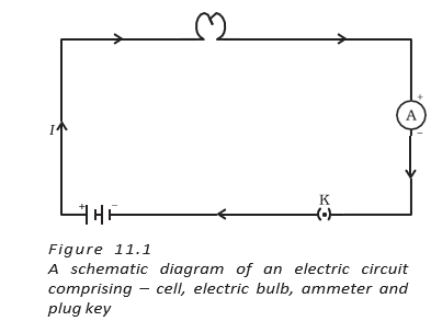
Electric circuit — A continuous, closed conducting path through which electric current can flow.
Circuit Basics
- Cell or battery: Provides the potential difference that drives charge through the circuit.
- Switch: Makes or breaks the conducting link in the circuit.
- Open circuit: A break in the path stops current; opening a torch switch makes its bulb go out.
Electric current — The rate at which electric charge flows through a cross-section of a conductor.
Current and Its Direction
- In metals: Moving electrons carry the charge that produces current.
- Conventional direction: Current is taken to flow from the positive terminal to the negative terminal of a cell through the external circuit.
- Electron flow: Electrons move in the direction opposite to conventional current.
- Current magnitude: If charge passes through a conductor’s cross-section in time , then .
Use this to calculate current, charge or time.
Units and Measurement of Current
- Charge unit: The SI unit is the coulomb (); is approximately the charge of electrons.
- Electron charge: One electron carries charge .
- Current unit: The SI unit is the ampere (); .
- Smaller units: and .
- Ammeter: Measures current and must be connected in series with the part of the circuit being measured.
For example, a current of flowing for transfers of charge.
Electric Potential and Potential Difference
Potential difference — The work done to move a unit charge from one point to another in a circuit.
What Drives Current?
- Cause of charge flow: A potential difference across a conductor sets its charges in motion.
- Water analogy: Water flows through a tube when a pressure difference exists; similarly, charge flows when an electric potential difference exists.
- Cell action: Chemical reactions inside a cell create potential difference across its terminals, even when no current is being drawn.
- Energy supply: When the cell drives current, it expends its stored chemical energy to maintain the current.
Here, is work done and is charge moved.
Unit and Measurement of Potential Difference
- SI unit: The volt (), named after Alessandro Volta.
- One volt: A potential difference of exists when of work moves of charge; .
- Voltmeter: Measures potential difference and is connected in parallel across the two points.
For example, moving across a potential difference of requires of work.
Quick recap
- Electric current is the rate of flow of charge: .
- Conventional current flows from positive to negative; electrons move the other way.
- A circuit must be closed for current to flow; a switch opens or closes its conducting path.
- An ammeter is connected in series to measure current.
- Potential difference drives charge flow and is defined by .
- A voltmeter is connected in parallel; .
Circuit Diagram
Circuit Diagrams and Symbols
Circuit diagram — A circuit diagram is a schematic representation of an electric circuit using conventional symbols for its components.
Common circuit symbols
- Cell and battery: A cell is shown by two unequal parallel lines; the longer line is positive and the shorter is negative. A battery has several such pairs.
- Switch: An open switch has an unconnected gap; a closed switch has connected contacts.
- Wires: A dot marks joined wires. Crossing wires shown with a bridge and no dot are not joined.
- Components: A bulb is shown by a lamp symbol; a resistor by a zigzag; a variable resistor by a zigzag with an adjustment arrow.
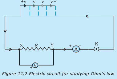
- Meters: An ammeter is a circle marked and a voltmeter a circle marked ; both have positive and negative terminals.
Ohm’s Law
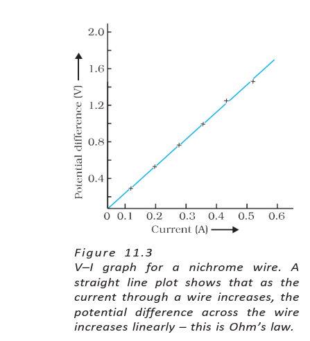
Ohm’s law — At constant temperature, the potential difference across a metallic conductor is directly proportional to the current through it.
Key points
- Relationship: For a given conductor at constant temperature, the ratio remains constant.
- Graph: The – graph is a straight line through the origin, showing that voltage increases linearly with current.
- Name and date: German physicist Georg Simon Ohm established this relationship in 1827.
Use these relations when voltage, current or resistance is known.
Resistance and Variable Resistance
Resistance — Resistance is the property of a conductor that opposes the flow of electric charges.
Resistance and current
- Symbol and unit: Resistance is represented by and its SI unit is the ohm, symbol .
- One ohm: A conductor has resistance when a potential difference of produces a current of .
- Effect at fixed voltage: Current is inversely proportional to resistance; if resistance doubles, current halves.
The unit definition follows directly from the resistance relation.
Variable resistance — Variable resistance is a component used to regulate current without changing the voltage source.
Rheostat
- Rheostat: A device used in a circuit to change its resistance and thereby adjust the current.
Resistance in Different Materials
Why components differ
- Different currents: Components in the same circuit can produce different current readings because they offer different levels of resistance.
- Cause of resistance: Electrons moving through a conductor are hindered by attractions from the atoms in the material.
- Comparison for equal-sized components: Lower resistance means better conduction; higher resistance means poorer conduction.
| Type | Resistance | Description |
|---|---|---|
| Good conductor | Low | Allows electric current to flow easily. |
| Resistor | Appreciable | Offers noticeable opposition to current. |
| Poor conductor | Higher | Offers greater resistance than an equal-sized good conductor. |
| Insulator | Even higher | Offers still greater resistance than an equal-sized poor conductor. |
State Ohm’s law and write its mathematical form.
Define one ohm of resistance.
Quick recap
- Circuit diagrams represent components using conventional symbols; a dot marks a wire joint.
- An ammeter measures current and a voltmeter measures potential difference across a component.
- At constant temperature, Ohm’s law gives and a straight-line – graph through the origin.
- Resistance opposes charge flow; its SI unit is the ohm, .
- At fixed voltage, increasing resistance decreases current; a rheostat adjusts circuit resistance.
- For equal-sized components, resistance increases from good conductors to poor conductors and insulators.
Factors on Which the Resistance of a Conductor Depends
Factors Affecting Resistance
Electrical resistivity — Resistivity, , is a characteristic property of a material that relates a conductor’s resistance to its length and cross-sectional area.
Use for a uniform conductor. SI unit of resistivity: .
Resistivity of Materials
- Conductors: Metals and alloys generally have low resistivity, about to .
- Insulators: Rubber and glass have very high resistivity, about to .
- Alloys: Their resistivity is generally higher than that of their constituent metals. They resist oxidation at high temperatures, making them useful in heating devices.
- Uses: Nichrome is used in heating devices such as irons and toasters; tungsten is used in bulb filaments; copper and aluminium are used in transmission lines.
| Category | Material | Resistivity () |
|---|---|---|
| Conductor | Silver | |
| Conductor | Copper | |
| Conductor | Aluminium | |
| Conductor | Tungsten | |
| Conductor | Nickel | |
| Conductor | Iron | |
| Conductor | Chromium | |
| Conductor | Mercury | |
| Conductor | Manganese | |
| Alloy | Constantan (Cu and Ni) | |
| Alloy | Manganin (Cu, Mn and Ni) | |
| Alloy | Nichrome (Ni, Cr, Mn and Fe) | |
| Insulator | Glass | – |
| Insulator | Hard rubber | – |
| Insulator | Ebonite | – |
| Insulator | Diamond | – |
| Insulator | Dry paper |
Applying Ohm’s Law and the Resistance Formula
Use to find current when voltage and resistance are known.
Current from a Source
- Bulb: With filament resistance , the current is .
- Heater: With coil resistance , the current is .
- Key point: At the same voltage, the lower-resistance heater draws more current.
Current When Voltage Changes
- Given: A heater draws at , so its resistance is .
- At : .
For wire diameter , use this area to calculate resistivity from resistance.
Finding a Wire’s Resistivity
- Given: , and diameter .
- Calculation: .
- Identification: This resistivity matches manganese in the table.
How Dimensions Change Resistance
- First wire: For a material with resistivity , length and area , .
- Second wire: Its length is and area is , so .
Resistance of a System of Resistors
Ways of Connecting Resistors
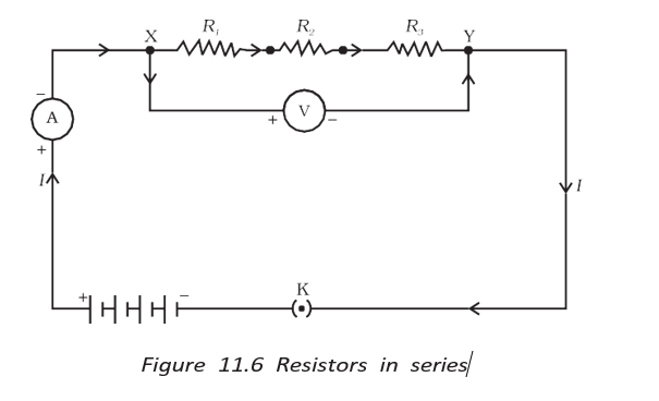
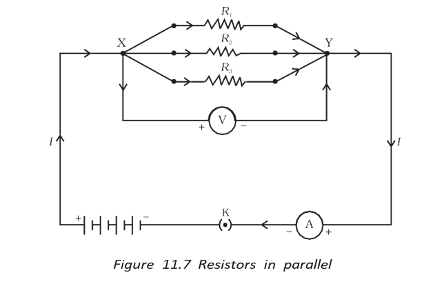
- Series connection: Resistors joined end to end form a series combination.
- Parallel connection: Resistors connected between the same two points form a parallel combination.
State the factors on which the resistance of a uniform conductor depends.
Why are alloys commonly used in electrical heating devices?
A wire’s length is halved and its cross-sectional area doubled. How does its resistance change?
Quick recap
- Resistance increases with length and decreases with cross-sectional area: .
- Resistivity is a material property measured in ; resistance and resistivity vary with temperature.
- Metals and alloys generally have low resistivity; insulators have very high resistivity.
- Alloys resist oxidation at high temperatures and are useful in heating appliances; tungsten is used in bulb filaments.
- Ohm’s law gives current as ; at a fixed voltage, lower resistance means greater current.
- Resistors can be connected in series (end to end) or in parallel (across the same two points).
Resistors in Series
Series Combination
Current and potential difference
- Series connection: Resistors are joined end-to-end, forming a single path for current.
- Current: The same current flows through every resistor in the circuit.
- Potential difference: The total potential difference is the sum of the drops across individual resistors: .
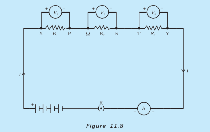
The equivalent resistance is the sum of all resistances connected in series.
Equivalent resistance
- Equivalent resistor: A single resistor can replace a series group if it maintains the same current for the same potential difference.
- Ohm’s law: For the whole circuit, ; for each resistor, .
- Result: The series equivalent resistance is greater than any individual resistance.
Series-circuit example
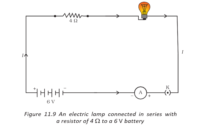
- Given: A lamp and a conductor are connected in series to a battery.
- Total resistance and current: ; .
- Potential differences: Lamp: ; conductor: . Their sum is .
Parallel Combination
Current and potential difference
- Parallel connection: Resistors are connected across the same two points, forming separate branches.
- Potential difference: Each resistor has the same potential difference as the parallel combination.
- Current: Total current divides among the branches: .
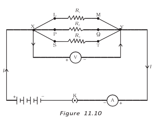
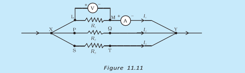
The reciprocal of equivalent resistance equals the sum of the reciprocals of the branch resistances.
Ohm’s law and equivalent resistance
- Whole combination: ; for each branch, .
- Result: Parallel equivalent resistance is lower than the resistance of any individual branch.
Parallel-circuit example
- Given: , , and are connected in parallel across .
- Branch currents: ; ; .
- Total current and resistance: ; .
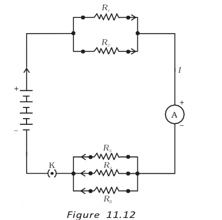
Combining parallel groups
- First group: and in parallel give .
- Second group: , , and in parallel give .
- Total circuit: The equivalent groups are in series, so ; with a battery, .
| Point | Series | Parallel |
|---|---|---|
| Current | Same through each resistor. | Divides among branches; branch currents add to the total. |
| Potential difference | Divides across resistors; individual drops add to the total. | Same across every branch. |
| Equivalent resistance | Sum of individual resistances; greater than any one resistance. | Reciprocal equals the sum of reciprocal branch resistances; less than the smallest branch resistance. |
Why parallel circuits are useful for electrical gadgets
- Different current needs: A series circuit forces the same current through every gadget, so it is unsuitable for devices needing widely different currents.
- Parallel branches: Current divides among the gadgets, allowing different branch currents according to their resistances.
- Reduced resistance: Adding parallel branches decreases the total resistance of the circuit.
Series-circuit limitation
- Component failure: If one component in a series circuit fails, the circuit breaks and none of the components works.
- Example: In a series string of fairy lights, a fused bulb can stop the entire string from working.
Do not add resistances directly in parallel: add their reciprocals, then take the reciprocal of the result.
State the current, potential-difference and equivalent-resistance rules for resistors in series.
State the equivalent-resistance rule for resistors connected in parallel.
Why is a series circuit unsuitable for an electric bulb and heater that need different currents?
Quick recap
- In series, current is the same through each resistor, potential drops add, and resistances add.
- In parallel, each branch has the same potential difference, while branch currents add.
- The reciprocal of parallel equivalent resistance is the sum of the reciprocals of the branch resistances.
- Series equivalent resistance is greater than any individual resistance; parallel equivalent resistance is smaller than the smallest branch resistance.
- Parallel combinations reduce total resistance and allow different currents in branches.
- A failed component breaks a series circuit, so none of its components work.
Heating Effect of Electric Current
Heating Effect of Electric Current — Core Idea
Heating effect of electric current — The conversion of electrical energy into heat when current flows through a resistor or conductor.
- Energy transfer: A cell supplies energy to maintain current. Some may do useful work, while some is dissipated as heat.
- Purely resistive circuit: When the circuit contains only resistors, the supplied electrical energy is entirely converted into heat.
- Everyday observation: An electric fan or other appliance may become warm after operating continuously.
- Uses: The heating effect is used in devices such as electric heaters and irons.
Power and Joule’s Law of Heating
- Work done: Moving charge through potential difference requires energy . If this happens in time , the source’s power input is .
- Heat produced: In a resistor, the electrical energy supplied in time is dissipated as heat.
- Circuit diagram: The ammeter is connected in series and the voltmeter in parallel with the resistor.
Power supplied by the source.
For a steady current, the heat produced in a resistor over time .
Using Ohm’s law, heat produced in a resistor is given by this relation.
- Current: For fixed and , heat is proportional to the square of current: .
- Resistance: For fixed and , heat is proportional to resistance: .
- Time: For fixed and , heat is proportional to the duration of current flow: .
- Known voltage: Find current using , then use Joule’s law to calculate heat.
Example calculations
- Electric iron: At , power settings of and draw currents of and , respectively, using .
- Iron resistance: Using , the corresponding resistances are at maximum heating and at minimum heating.
- Finding voltage from heat: If is produced in by a resistor, ; hence .
Practical Applications of Heating Effect
- Unwanted heating: It can waste useful electrical energy, raise component temperatures and alter their properties.
- Heating appliances: Laundry irons, toasters, ovens, kettles and electric heaters use Joule heating.
| Feature | Electric bulb | Fuse |
|---|---|---|
| Purpose | Uses heating to produce light. | Uses heating to interrupt an excessively high current and protect circuits and appliances. |
| Key material or construction | A strong tungsten filament has a high melting point of ; it is thermally insulated and enclosed with chemically inactive nitrogen and argon gases. | A wire of suitable melting point, made from a metal or alloy such as aluminium, copper, iron or lead; commonly enclosed in a porcelain cartridge with metal ends. |
| Effect of current | The filament becomes very hot and emits light; most consumed power becomes heat, with a small part radiated as light. | Current above the fuse rating heats and melts the wire, breaking the circuit. |
| Connection | Filament forms part of the bulb circuit. | Connected in series with the device it protects. |
Fuse rating example
- Domestic ratings: Common fuse ratings include , , , and .
- Electric iron: A iron at draws ; use a fuse.
Do not confuse a fuse’s series connection with the voltmeter’s parallel connection: a fuse must be in series so that it can break the device’s current path.
Quick recap
- Electrical energy supplied to a resistive circuit is dissipated as heat.
- Power is ; heat supplied in time is .
- Joule’s law is : heat varies as , and under the stated fixed conditions.
- Heating is useful in appliances and bulbs, but unwanted heating may damage or alter circuit components.
- A fuse is connected in series and melts when current exceeds its rating, protecting the circuit.
Electric Power
Electric Power
Use the form that matches the known circuit quantities.
Units of Power and Electrical Energy
Use consistent power and time units.
Commercial Unit of Electrical Energy
- Watt-hour: is the energy used by a device operating for hour.
- Commercial unit: The kilowatt-hour (), commonly called one “unit,” is used to measure electrical energy consumption.
- Conversion: .
Worked Applications
- Bulb: At 220 V and 0.50 A, its power is 110 W.
- Refrigerator: A 400 W refrigerator used for 8 hours daily consumes 96 kWh in 30 days.
- Cost: At Rs 3 per kWh, that refrigerator’s 30-day energy cost is Rs 288.
Quick recap
- Electric power is the rate of electrical energy consumption: .
- Equivalent power formulas are and .
- The SI unit is the watt; and .
- Electrical energy is calculated using .
- The commercial energy unit is the kWh, and .
- For electricity costs, convert energy use to kWh and multiply by the cost per kWh.
Science — ALL CHAPTERS
1
CHEMICAL REACTIONS AND EQUATIONS
2
ACIDS, BASES AND SALTS
3
METALS AND NON-METALS
4
CARBON AND ITS COMPOUNDS
5
LIFE PROCESSES
6
CONTROL AND COORDINATION
7
HOW DO ORGANISMS REPRODUCE?
8
HEREDITY
9
LIGHT – REFLECTION AND REFRACTION
10
THE HUMAN EYE AND THE COLOURFUL WORLD
11
ELECTRICITY
12
MAGNETIC EFFECTS OF ELECTRIC CURRENT
13
OUR ENVIRONMENT