Class 10 . Science . Science . Light Reflection and Refraction
Chapter 9: LIGHT – REFLECTION AND REFRACTION
Ch 9
Science
Class 10
Introduction & Reflection of Light
How We See Objects
Seeing and propagation of light
- Visibility: We see an object when light reflected from it reaches our eyes.
- Transmission: We can see through a transparent medium because light passes through it.
- Straight-line propagation: Light appears to travel in straight lines; a small source can produce a sharp shadow behind an opaque object.
- Ray: A ray is a straight-line representation of the path followed by light.
- Limitation: Light can bend around a very small obstacle; this diffraction means the simple straight-ray model is insufficient for such effects.
Light’s behaviour
- Optics: Reflection and refraction are studied using the straight-line propagation of light.
- Wave and particle descriptions: Light shows wave-like behaviour, while its interaction with matter can also show particle-like behaviour; modern quantum theory accounts for both aspects.
Reflection of Light
Laws of reflection
- First law: The angle of incidence equals the angle of reflection.
- Second law: The incident ray, reflected ray and normal at the point of incidence lie in the same plane.
- Scope: Both laws apply to all reflecting surfaces, including spherical mirrors.
Angles are measured from the normal.
Image formed by a plane mirror
- Nature: The image is virtual and erect.
- Size and distance: It is the same size as the object and lies as far behind the mirror as the object is in front.
- Orientation: The image is laterally inverted.
Spherical Mirrors
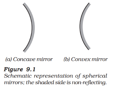
Spherical mirror — A mirror whose reflecting surface forms part of a sphere.
| Type | Reflecting surface | Position of centre of curvature |
|---|---|---|
| Concave mirror | Curves inward; faces the centre of the sphere | In front of the mirror |
| Convex mirror | Curves outward | Behind the mirror |
Parts and Key Terms
| Term | Meaning |
|---|---|
| Pole () | Centre of the reflecting surface; it lies on the mirror. |
| Centre of curvature () | Centre of the sphere of which the mirror is a part; it is not on the mirror. |
| Radius of curvature () | Radius of that sphere; the distance equals . |
| Principal axis | Straight line through and ; it is normal to the mirror at . |
| Principal focus () | Point on the principal axis where rays parallel to it converge, or appear to diverge from, after reflection. |
| Focal length () | Distance between the pole and the principal focus. |
| Aperture | Diameter of the reflecting surface. |
Principal focus and sunlight
- Concave mirror: Parallel rays reflected from the mirror meet at the principal focus, so the focus is real.
- Convex mirror: Reflected parallel rays spread out and appear to come from the principal focus, so the focus is virtual.
- Sunlight example: A concave mirror concentrates sunlight at its focus, forming a bright spot that can heat and ignite paper.
- Focal length estimate: The distance from the mirror to the Sun’s focused image gives an approximate focal length.
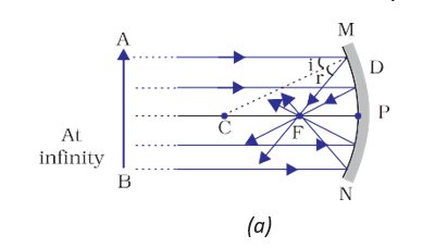
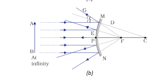
For spherical mirrors whose aperture is much smaller than the radius of curvature, the focus lies midway between the pole and centre of curvature.
Do not confuse the centre of curvature with a point on the mirror: it is the centre of the sphere, while the pole is on the reflecting surface.
State the two laws of reflection.
How do the principal foci of concave and convex mirrors differ?
Quick recap
- Objects are seen when reflected light reaches the eyes; transparent media transmit light.
- Light appears to travel in straight lines and is represented by rays.
- The angle of incidence equals the angle of reflection, and the rays and normal lie in one plane.
- Plane-mirror images are virtual, erect, same-sized, equally distant from the mirror, and laterally inverted.
- Concave mirrors curve inward; convex mirrors curve outward.
- A concave mirror converges parallel rays at a real focus; a convex mirror’s rays appear to diverge from a virtual focus.
- For a spherical mirror whose aperture is much smaller than its radius of curvature, .
Image Formation by Spherical Mirrors
Images Formed by a Concave Mirror
Real image — A real image forms where reflected light rays actually meet; it is usually inverted and can be obtained on a screen.
Virtual image — A virtual image forms where reflected rays appear to meet; it cannot be obtained on a screen and is erect.
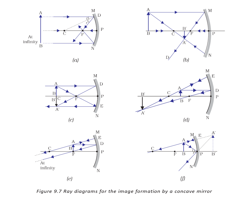
- Image depends on position: A concave mirror can form real or virtual images, with different sizes and positions, depending on where the object is placed.
- Small-aperture relation: For a spherical mirror of small aperture, the principal focus lies midway between the pole and centre of curvature .
| Object position | Image position | Image size | Nature |
|---|---|---|---|
| At infinity | At focus | Highly diminished; point-sized | Real and inverted |
| Beyond | Between and | Diminished | Real and inverted |
| At | At | Same size | Real and inverted |
| Between and | Beyond | Enlarged | Real and inverted |
| At | At infinity | Highly enlarged | Real and inverted |
| Between and | Behind the mirror | Enlarged | Virtual and erect |
Ray Rules for Spherical Mirrors
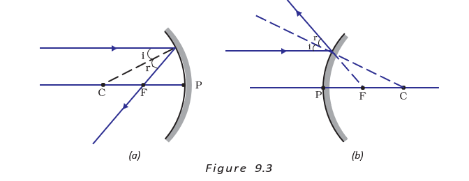
Ray diagram — A ray diagram locates an image by tracing reflected rays; two suitable rays from a point on the object are enough.
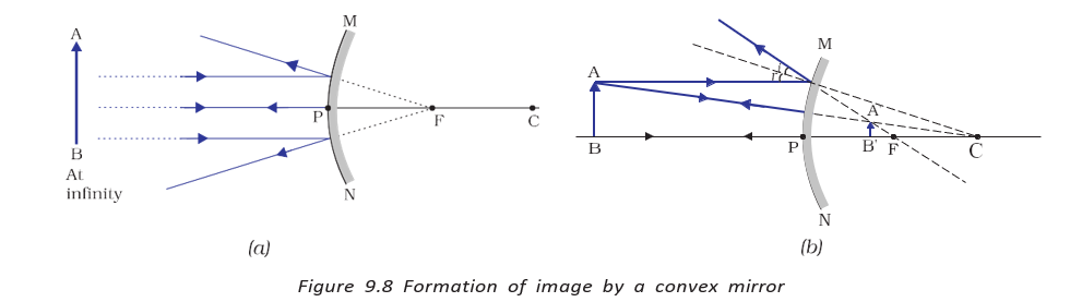
- Parallel ray: A ray parallel to the principal axis reflects through in a concave mirror; in a convex mirror, it appears to come from .
- Focus ray: A ray through in a concave mirror, or directed towards in a convex mirror, reflects parallel to the principal axis.
- Centre-of-curvature ray: A ray through in a concave mirror, or directed towards in a convex mirror, reflects back along its path because it is incident along the normal.
- Pole ray: At pole , the incident and reflected rays make equal angles with the principal axis, following the law of reflection.
- Image location: The point where reflected rays meet gives the image; if they diverge, extend them behind the mirror to locate a virtual image.
Uses of Concave Mirrors
- Lighting: Concave mirrors in torches, search-lights and vehicle headlights produce powerful parallel beams.
- Magnification: Shaving mirrors and dentists’ mirrors provide enlarged images of the face and teeth.
- Solar furnaces: Large concave mirrors concentrate sunlight to produce heat.
Images Formed by a Convex Mirror
Convex-mirror image — A convex mirror forms a virtual, erect and diminished image behind the mirror for all object positions.
| Object position | Image position | Image size | Nature |
|---|---|---|---|
| At infinity | At , behind the mirror | Highly diminished; point-sized | Virtual and erect |
| Between infinity and pole | Between and , behind the mirror | Diminished | Virtual and erect |
- Object moves farther away: The image becomes smaller and moves closer to .
Wide Field of View and Uses of Convex Mirrors
Why are convex mirrors used as rear-view mirrors in vehicles?
Do not assume every concave-mirror image is real: an object between and forms an enlarged, virtual and erect image behind the mirror.
Quick recap
- For a small-aperture spherical mirror, lies midway between and .
- A concave mirror’s image position, size and nature depend on the object’s position relative to , and .
- For a concave mirror, an object between and gives an enlarged, virtual, erect image behind the mirror.
- Two reflected rays are sufficient to locate an image in a ray diagram.
- A convex mirror always forms a diminished, virtual and erect image behind the mirror.
- Convex mirrors are used for rear views because they provide a wide field of view.
Sign Convention for Reflection by Spherical Mirrors
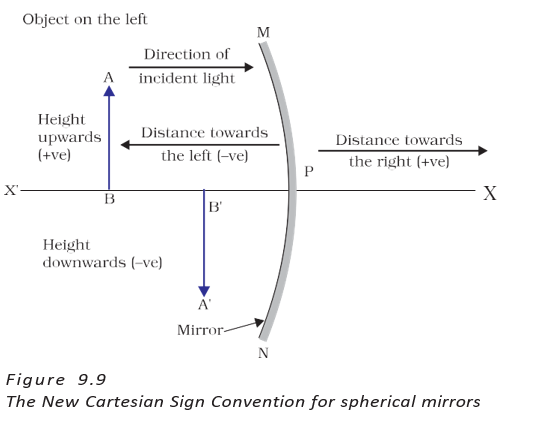
New Cartesian Sign Convention
New Cartesian Sign Convention — A consistent system for assigning signs to distances and heights in spherical-mirror calculations.
| Quantity or direction | Sign |
|---|---|
| Pole | Origin; all axial distances are measured from it |
| Principal axis | The -axis |
| Right of the pole | Positive, along the direction |
| Left of the pole | Negative, along the direction |
| Above the principal axis | Positive, along the direction |
| Below the principal axis | Negative, along the direction |
| Object and incident light | The object is placed to the left; light falls on the mirror from the left |
Distances and mirror types
- Object distance (): Distance from the pole to the object; with the object on the left, is negative.
- Image distance (): Distance from the pole to the image; an image in front of the mirror is negative, while one behind it is positive.
- Focal length (): Distance from the pole to the principal focus. It is negative for a concave mirror and positive for a convex mirror.
- Radius of curvature (): For a spherical mirror, ; use the same sign convention for and .
Mirror Formula
Mirror formula — The relation connecting object distance , image distance and focal length for spherical mirrors.
Valid for all spherical mirrors and object positions. Substitute signed values using the New Cartesian Sign Convention.
Magnification
Magnification — The ratio of image height to object height, showing how large the image is relative to the object.
Here, is object height and is image height. Positive indicates an erect image; negative indicates an inverted image. The magnitude gives the size ratio.
Applying the formulas
- Convex-mirror example: With and , . The mirror formula gives .
- Result: The image is behind the mirror. , so it is virtual, erect and times the object's height.
- Concave-mirror example: For , and , the mirror formula gives .
- Result: Place the screen in front of the mirror. , so ; the real image is inverted and enlarged.
Do not substitute unsigned distances: an object placed in front of the mirror has negative , and the signs of , and image height must follow the convention.
Refraction of Light
Refraction of light — The change in the direction of light as it travels obliquely from one transparent medium into another.
Everyday effects of refraction
- Pencil in water: The submerged part appears displaced at the air–water boundary because light from it reaches the eye from a changed direction.
- Coin under water: The coin appears raised and can become visible from a viewing position where it was previously hidden.
- Text under glass: Letters viewed through a glass slab appear raised; the effect varies with the pair of media.
- Media matter: Replacing water with kerosene or turpentine, or glass with plastic, can change the extent of the apparent displacement.
State the New Cartesian Sign Convention for distances and heights.
Write the mirror formula and the magnification relation for a spherical mirror.
Quick recap
- Measure all axial distances from the mirror's pole; right is positive and left is negative.
- Heights above the principal axis are positive; heights below it are negative.
- Use for spherical mirrors with signed values.
- Magnification is ; its sign indicates image orientation.
- Refraction is the change in light direction when it travels obliquely between transparent media.
- Refraction explains why submerged objects and text under glass appear raised or displaced.
Refraction Through a Rectangular Glass Slab
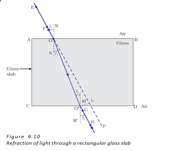
Refraction through a rectangular glass slab
Refraction — The change in direction of light as it passes from one transparent medium to another because its speed changes.
Ray path through a glass slab
- First face: At the air–glass boundary, light enters a denser medium and bends towards the normal.
- Second face: At the glass–air boundary, light enters a rarer medium and bends away from the normal.
- Emergent ray: The ray leaving the slab is parallel to the incident ray because the parallel faces cause equal and opposite bending.
- Lateral displacement: The emergent ray is shifted sideways from the original path.
Laws of refraction
- First law: The incident ray, refracted ray and normal at the point of incidence all lie in the same plane.
- Snell’s law: For a given colour of light and a given pair of media, the ratio of the sine of the angle of incidence to the sine of the angle of refraction is constant, for .
- Refractive index: This constant is the refractive index of the second medium with respect to the first.
Here, is the angle of incidence and is the angle of refraction.
Refractive index
Refractive index — A measure of how much light changes direction when it travels between a given pair of media; it is related to the relative speeds of light in those media.
Relative refractive index
- Notation: is the refractive index of medium 2 with respect to medium 1; and are the speeds of light in the respective media.
- Reciprocal relation: The refractive indices of the two media with respect to each other are reciprocals.
Use when comparing the speeds of light in the two media.
This is the reciprocal of .
Absolute refractive index
- Reference medium: When medium 1 is vacuum or air, the refractive index of the other medium is called its absolute refractive index.
- Light speed: Light travels fastest in vacuum at ; its speed is only slightly lower in air and considerably lower in water or glass.
Here, is the speed of light in air and is its speed in the medium.
| Material | Refractive index |
|---|---|
| Air | 1.0003 |
| Ice | 1.31 |
| Water | 1.33 |
| Alcohol | 1.36 |
| Kerosene | 1.44 |
| Fused quartz | 1.46 |
| Turpentine oil | 1.47 |
| Benzene | 1.50 |
| Crown glass | 1.52 |
| Canada balsam | 1.53 |
| Rock salt | 1.54 |
| Carbon disulphide | 1.63 |
| Dense flint glass | 1.65 |
| Ruby | 1.71 |
| Sapphire | 1.77 |
| Diamond | 2.42 |
Optical density is not the same as mass density: kerosene has a higher refractive index than water, so it is optically denser, even though its mass density is lower.
Quick recap
- Refraction occurs because light changes speed as it enters another transparent medium.
- Air-to-glass refraction bends light towards the normal; glass-to-air refraction bends it away.
- A slab’s emergent ray is parallel to the incident ray but laterally displaced.
- The incident ray, refracted ray and normal lie in one plane.
- Snell’s law gives for a given colour and pair of media.
- Relative refractive index is the ratio of light speeds; absolute refractive index is .
- Optical density does not necessarily match mass density; kerosene is optically denser than water.
Refraction by Spherical Lenses
Lens Types and Basic Terms
Spherical lens — A transparent material bounded by two surfaces, at least one of which is spherical, forms a lens.
Lens shapes and properties
- Convex lens: Its surfaces bulge outward; it is thicker at the middle than at the edges and converges light rays.
- Concave lens: Its surfaces curve inward; it is thicker at the edges than at the middle and diverges light rays.
- Centres of curvature: The centres of the spheres of which the two curved lens surfaces form parts; denoted by and .
- Principal axis: The imaginary straight line passing through and .
- Optical centre (): The central point of the lens; a ray passing through it emerges without deviation.
- Aperture: The effective diameter of the circular outline of the lens.
| Lens | Surface shape and thickness | Effect on parallel rays |
|---|---|---|
| Convex | Surfaces bulge outward; thicker at the middle | Converges rays; also called a converging lens |
| Concave | Surfaces curve inward; thicker at the edges | Diverges rays; also called a diverging lens |
Thin lenses and principal focus
- Thin lens with small aperture: Its aperture is much smaller than its radius of curvature, and its two centres of curvature are equally distant from .
- Principal focus (): For a convex lens, parallel rays converge at this point; for a concave lens, they appear to diverge from it.
- Two principal foci: A lens has a focus on each side, denoted by and .
- Focal length (): The distance from the optical centre to a principal focus.
- Approximate focal length: Sunlight is nearly parallel, so the distance from the lens to its sharp image of the Sun is approximately .
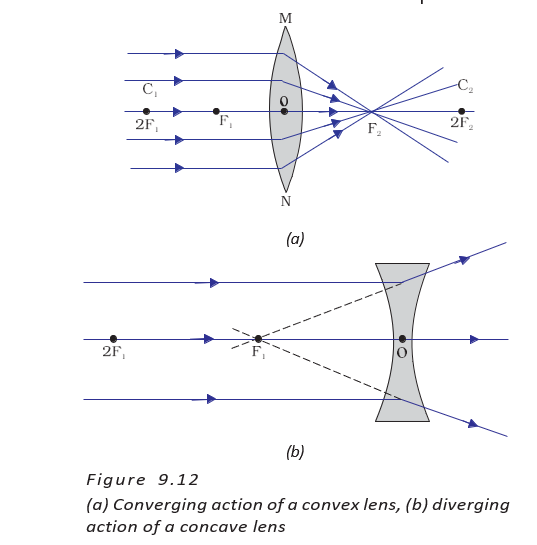
For sunlight, the distance from the lens to the sharp image is approximately the focal length.
Focusing sunlight with a convex lens
- Image: A convex lens brings parallel sunlight rays together at a bright, sharp spot; this spot is a real image of the Sun.
- Heating effect: Concentrating sunlight at one point generates enough heat to make paper smoke and possibly catch fire.
Image Formation by Lenses
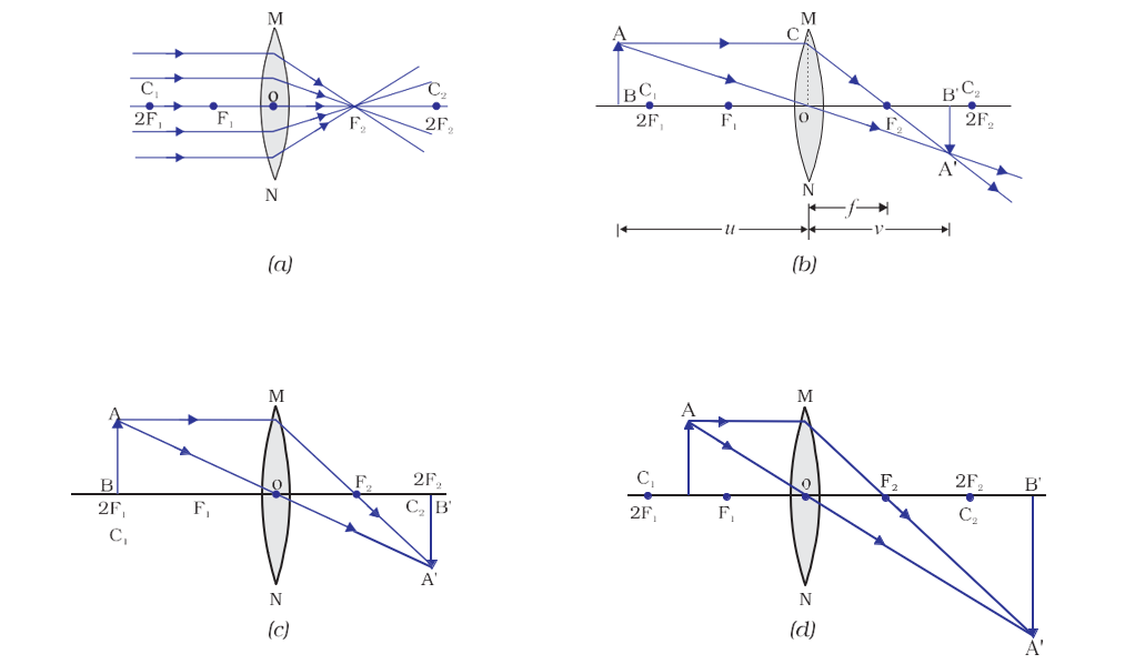
| Object position | Image position | Relative size | Nature |
|---|---|---|---|
| At infinity | At focus | Highly diminished, point-sized | Real and inverted |
| Beyond | Between and | Diminished | Real and inverted |
| At | At | Same size | Real and inverted |
| Between and | Beyond | Enlarged | Real and inverted |
| At focus | At infinity | Infinitely large or highly enlarged | Real and inverted |
| Between focus and optical centre | Same side of the lens as the object | Enlarged | Virtual and erect |
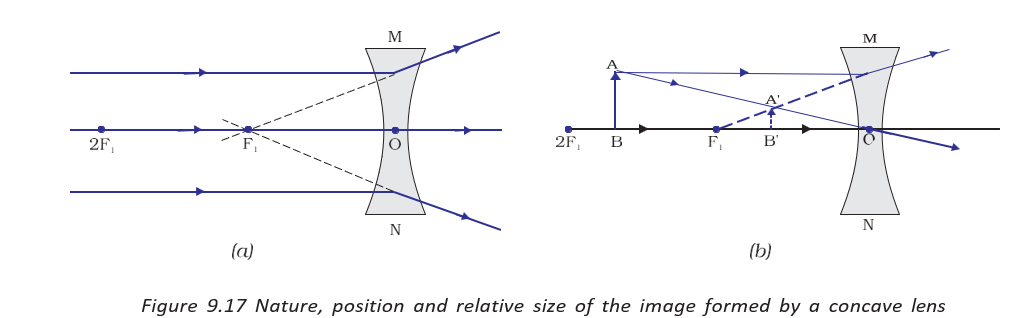
| Object position | Image position | Relative size | Nature |
|---|---|---|---|
| At infinity | At focus | Highly diminished, point-sized | Virtual and erect |
| Between infinity and optical centre | Between focus and optical centre | Diminished | Virtual and erect |
- Concave lens: Always forms a virtual, erect and diminished image, whatever the object position.
- Convex lens: Forms a virtual, erect and enlarged image only when the object is between and ; otherwise, the images listed above are real and inverted.
Ray Diagram Rules
Principal rays for constructing images
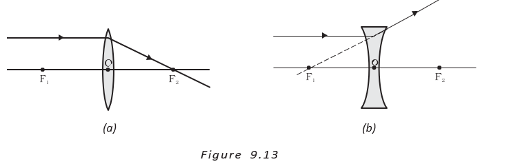
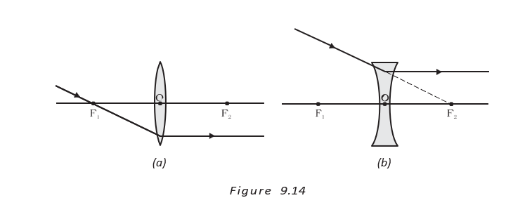
- Parallel ray: A ray parallel to the principal axis refracts through the far focus of a convex lens; after a concave lens it appears to come from the near focus.
- Focus ray: A ray passing through the principal focus of a convex lens emerges parallel to the axis. For a concave lens, a ray directed toward the far focus emerges parallel.
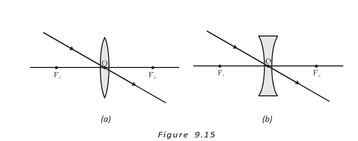
- Optical-centre ray: A ray passing through emerges without deviation.
Sign Convention
- Reference point: Measure all lens distances from the optical centre .
- Focal length: It is positive for a convex lens and negative for a concave lens.
- Apply signs carefully: Use the sign convention for object distance , image distance , focal length , object height and image height .
State the principal-focus rule for a convex and a concave lens.
Describe the image formed by a convex lens when the object is between and .
What image does a concave lens always form?
Quick recap
- A convex lens has outward-bulging surfaces, is thicker in the middle and converges light; a concave lens has inward-curved surfaces, is thicker at the edges and diverges light.
- The principal axis joins and ; the optical centre is , and focal length is measured from to a focus.
- A convex lens can form real, inverted images or, with an object inside , a virtual, erect, enlarged image.
- A concave lens always forms a virtual, erect, diminished image.
- Use the parallel, focus and optical-centre rays to construct lens ray diagrams.
- A convex lens focuses sunlight to form a real image of the Sun; the concentrated heat can burn paper.
- Measure lens distances from ; convex-lens focal length is positive and concave-lens focal length is negative.
Lens Formula and Magnification
Lens Formula
Lens formula — The lens formula relates object distance , image distance and focal length for a spherical lens.
Valid for spherical lenses; use the correct signs for , and .
Magnification
Magnification — Magnification is the ratio of image height to object height .
The sign indicates image orientation: positive means erect; negative means inverted.
Worked applications
- Concave lens: Given and , the lens formula gives ; the object is from the lens.
- Image from the concave lens: . The positive magnification indicates an erect, virtual image one-third the object's size.
- Convex lens: For , and , the lens formula gives .
- Image size and nature: , so . The image is real, inverted, tall and formed on the other side of the lens; it is twice enlarged.
Power of a Lens
Power of a lens — Power measures how strongly a lens converges or diverges light and is the reciprocal of its focal length.
Use focal length in metres to obtain power in dioptres. .
| Lens | Power sign | Example |
|---|---|---|
| Convex | Positive | gives |
| Concave | Negative | gives |
Lenses in contact
- Net power: For lenses in contact, add their individual powers algebraically: .
- Example: Lenses of and together have power .
- Use: Combining lens powers helps opticians determine corrective-lens power and is useful in designing camera, microscope and telescope lens systems.
A lens has power . Identify the lens and find its focal length.
Quick recap
- The lens formula is ; apply the correct sign convention.
- Lens magnification is .
- Positive magnification indicates an erect image; negative magnification indicates an inverted image.
- Lens power is when is measured in metres; its SI unit is the dioptre ().
- Convex lenses have positive power and concave lenses have negative power.
- For lenses in contact, the net power is the algebraic sum of their individual powers.
Science — ALL CHAPTERS
1
CHEMICAL REACTIONS AND EQUATIONS
2
ACIDS, BASES AND SALTS
3
METALS AND NON-METALS
4
CARBON AND ITS COMPOUNDS
5
LIFE PROCESSES
6
CONTROL AND COORDINATION
7
HOW DO ORGANISMS REPRODUCE?
8
HEREDITY
9
LIGHT – REFLECTION AND REFRACTION
10
THE HUMAN EYE AND THE COLOURFUL WORLD
11
ELECTRICITY
12
MAGNETIC EFFECTS OF ELECTRIC CURRENT
13
OUR ENVIRONMENT