Class 10 . Science . Science . Magnetic Effects of Electric Current
Chapter 12: MAGNETIC EFFECTS OF ELECTRIC CURRENT
Ch 12
Science
Class 10
Introduction & Magnetic Field and Field Lines
Electric Current Produces a Magnetic Effect
Link between electricity and magnetism
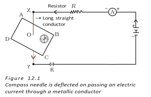
- Magnetic effect: A compass needle deflects when placed near a wire carrying electric current, showing that the current produces a magnetic effect.
- Connection: Electricity and magnetism are linked phenomena. In 1820, Hans Christian Oersted accidentally observed compass deflection near a current-carrying wire.
- Reverse effect: Moving magnets can produce an electric effect; this electromagnetic effect is also studied in the chapter.
- Electromagnets: These involve the magnetic effect of electric current.
Magnetic Field and Magnetic Field Lines
Magnetic field — The region around a magnet where its magnetic force can be detected.
Compass and magnetic poles
- Compass needle: A small bar magnet whose ends point approximately north and south.
- North-seeking pole: The end that points approximately north; the other end is the south-seeking pole.
- Pole interaction: Like poles repel; unlike poles attract.
Magnetic field lines — Lines used to represent the direction and relative strength of a magnetic field.
What field lines show
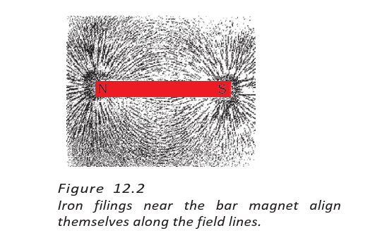
- Iron filings: Around a bar magnet, filings align in a pattern that reveals the magnetic field lines.
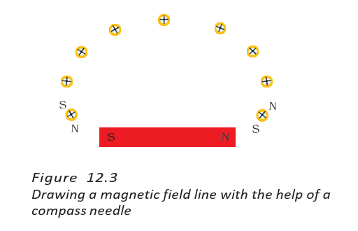
- Compass method: A compass placed at successive points shows the field direction; joining the marked positions gives a field line.
- Field quantity: A magnetic field has both direction and magnitude.
- Compass near a pole: Near a magnet’s north pole, the compass needle’s south pole points toward the magnet while its north pole points away.
Direction and shape of field lines
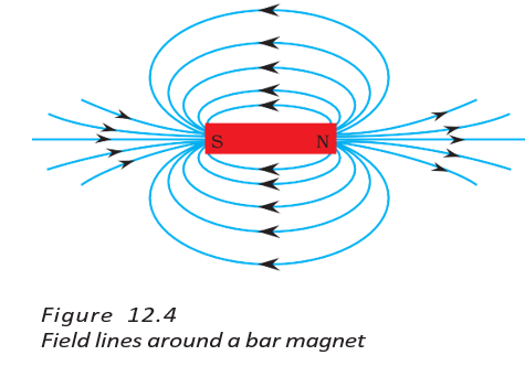
- Direction: A field line points in the direction a compass needle’s north pole moves.
- Outside a magnet: Field lines emerge from the north pole and enter the south pole.
- Inside a magnet: Field lines run from south pole to north pole, forming closed curves overall.
Strength and rules of field lines
- Strength: Closer, more crowded field lines indicate a stronger magnetic field and a greater force on a magnetic pole.
- No crossing: Two field lines never cross, because a compass needle at one point cannot point in two directions at once.
Why do magnetic field lines never cross?
Quick recap
- A current-carrying wire produces a magnetic effect, shown by a nearby compass needle’s deflection.
- Moving magnets can produce an electric effect; electromagnets use the magnetic effect of electric current.
- The magnetic field is the region around a magnet where its force can be detected.
- Iron filings and compass needles reveal the pattern and direction of magnetic field lines.
- Outside a magnet, field lines go north to south; inside, they go south to north, making closed curves.
- Crowded field lines indicate a stronger field, and field lines never cross.
Magnetic Field Due to a Current-carrying Arrying Conductor
Current Direction and Magnetic Field Direction
- Magnetic effect: An electric current flowing through a conductor produces a magnetic field around it.
- Direction: Reversing the current reverses the direction of the magnetic field.
Magnetic Field Around a Straight Conductor
- Field pattern: The magnetic field around a straight current-carrying conductor forms concentric circles centred on the wire.
- Field direction: A compass needle indicates the direction of the magnetic field at a point around the conductor.
Factors Affecting Magnetic Field Strength
What is the shape of the magnetic field around a straight current-carrying conductor?
How does the magnetic field change when current direction is reversed?
How do current and distance from the wire affect the magnetic field strength?
Quick recap
- A current-carrying conductor produces a magnetic field around it.
- Reversing the current reverses the magnetic-field direction.
- A straight wire produces concentric circular field lines.
- A compass needle indicates the field direction at its position.
- Greater current produces a stronger magnetic field.
- The magnetic field becomes weaker farther from the wire.
Right-hand Thumb Rule
Right-hand thumb rule — Hold a current-carrying straight conductor in your right hand with your thumb pointing in the direction of current; your curled fingers show the direction of the magnetic field lines around the conductor.
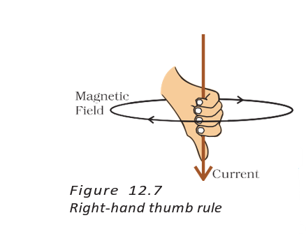
Power-line example
- Given: Current in a horizontal power line flows from east to west.
- Magnetic field: At points directly above and below the wire, viewed from the east end, the field circles clockwise; viewed from the west end, it circles anticlockwise.
Magnetic Field Due to a Current-Carrying Circular Loop
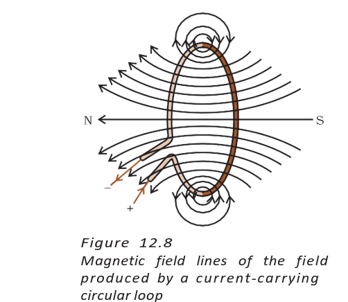
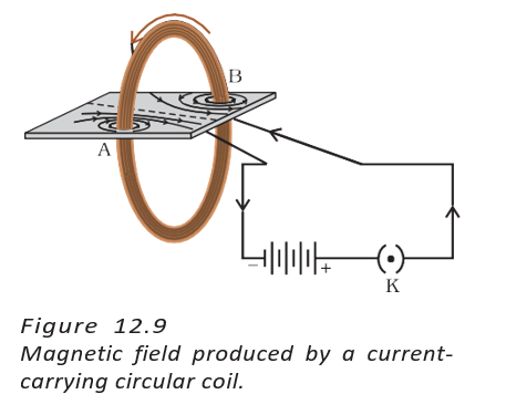
- Field pattern: Each small section of a current-carrying loop produces circular magnetic field lines around itself. Near the centre, the arcs appear almost straight.
- Direction at the centre: Applying the right-hand rule shows that every section of the loop contributes to the field in the same direction inside the loop.
- More turns: For a coil with turns, the magnetic field is times that of a single turn, because the fields from the turns add together.
- Field strength: The magnetic field produced by a current-carrying wire increases with the current and decreases with distance from the wire.
Magnetic Field Due to a Current in a Solenoid
Solenoid — A solenoid is a cylinder-shaped coil made of many closely wound turns of insulated copper wire.
- Bar-magnet-like pattern: A current-carrying solenoid has a north pole at one end and a south pole at the other.
- Inside the solenoid: The field lines are parallel and straight, showing that the magnetic field is uniform—equal in strength and direction throughout the interior.
- Electromagnet: Placing a magnetic material, such as soft iron, inside a solenoid lets its strong magnetic field magnetise the material; the resulting magnet is an electromagnet.
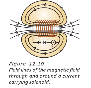
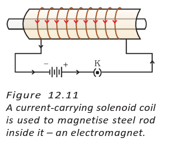
How does the magnetic field inside a solenoid compare with that around a bar magnet?
Quick recap
- The right-hand thumb rule gives the magnetic field direction around a straight current-carrying conductor.
- For east-to-west current, the field appears clockwise from the east end and anticlockwise from the west end.
- At the centre of a current-carrying loop, the field contributions from all sections point in the same direction.
- A coil with turns produces a field times that of a single turn.
- A current-carrying solenoid has a bar-magnet-like field pattern and a uniform field inside.
- A solenoid can magnetise soft iron placed inside it to form an electromagnet.
Force on a Current-carrying Conductor in a Magnetic Field
Force on a Current-Carrying Conductor
Force on a current-carrying conductor — A magnetic field exerts a force on a conductor carrying electric current.
Key observations
- Mutual force: A current-carrying conductor produces a magnetic field that can exert a force on a nearby magnet. Ampere suggested the magnet also exerts an equal and opposite force on the conductor.
- Direction: Reversing the current reverses the force; reversing the magnetic field also reverses the force.
- Maximum force: The force is greatest when the current and magnetic field are at right angles.
- Perpendicular directions: When current and field are perpendicular, the force is perpendicular to both.
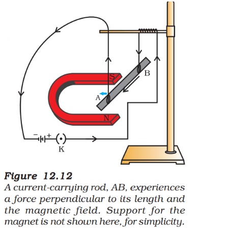
Fleming’s Left-Hand Rule
Fleming’s left-hand rule — Stretch the thumb, forefinger and middle finger of the left hand mutually perpendicular to indicate force, magnetic field and current.
| Finger | Direction represented |
|---|---|
| Forefinger | Magnetic field |
| Middle finger | Current |
| Thumb | Force or motion |
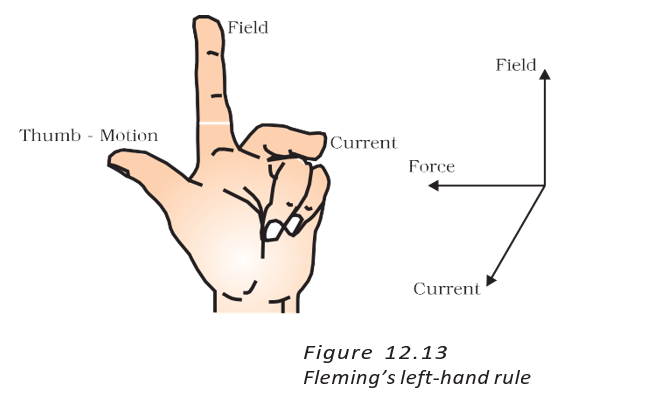
Applications and electron direction
- Applications: Electric motors, generators, loudspeakers, microphones and measuring instruments use current-carrying conductors in magnetic fields.
- Electron motion: Fleming’s rule uses conventional current, which is opposite to the direction in which electrons move.
- Example: For an electron moving downward in a magnetic field directed to the right, the force is into the page.
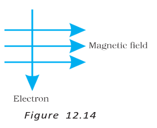
Magnetism in Medicine
- Body currents: Weak electric impulses travelling along nerve cells produce temporary magnetic fields, about one-billionth as strong as Earth’s magnetic field.
- Important organs: The heart and brain produce significant magnetic fields within the body.
- MRI: Magnetic Resonance Imaging uses magnetic fields to obtain images of body parts; analysing these images helps medical diagnosis.
Domestic Electric Circuits
Mains supply and wiring
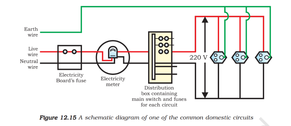
- Supply: Household electricity reaches homes through overhead lines or underground cables; the potential difference between live and neutral wires is 220 V.
- Live wire: Usually red-insulated; described in the text as positive.
- Neutral wire: Usually black-insulated; described in the text as negative.
- Circuit path: Supply wires pass through the main fuse, then the electricity meter and main switch, before connecting to household circuits.
- Separate circuits: A 15 A circuit is commonly used for higher-power appliances such as geysers and air coolers; a 5 A circuit is used for bulbs and fans.
| Wire | Usual insulation colour | Purpose |
|---|---|---|
| Live | Red | Carries supply to the appliance |
| Neutral | Black | Completes the circuit |
| Earth | Green | Safety connection for metal-bodied appliances |
Parallel connection and earthing
- Parallel appliances: Appliances are connected across live and neutral wires in parallel, so each receives the same potential difference and can be switched independently.
- Earth wire: It connects the metal body of an appliance to a metal plate buried in the earth.
- Protection: The earth wire provides a low-resistance path for leakage current, keeping the appliance body near earth potential and reducing the risk of severe electric shock.
Electric fuse — A safety device that melts and breaks the circuit when an excessively high current flows.
Overloading and short-circuiting
- Overloading: Current becomes excessive, for example due to a sudden rise in supply voltage or too many appliances connected to one socket.
- Short-circuiting: Direct contact between live and neutral wires—often from damaged insulation or an appliance fault—causes a sudden, large rise in current.
- Fuse action: Joule heating melts the fuse wire, breaking the circuit and protecting appliances and wiring from damage.
| Point | Overloading | Short-circuiting |
|---|---|---|
| Cause | Excess demand, such as too many appliances on one socket, or a supply-voltage rise | Live and neutral wires come into direct contact |
| Effect | Current exceeds the safe limit | Current rises abruptly to a very high value |
State Fleming’s left-hand rule.
How does an earth wire help protect a user?
Quick recap
- A magnetic field exerts a force on a current-carrying conductor; reversing current or field reverses the force.
- Fleming’s left-hand rule gives the directions of field, conventional current and force.
- Nerve impulses produce very weak magnetic fields; MRI uses magnetic fields to obtain images useful for diagnosis.
- Household appliances are connected in parallel so each gets the same potential difference and can be controlled separately.
- The earth wire reduces shock risk by providing a low-resistance path for leakage current.
- A fuse melts from Joule heating to break a circuit when excessive current flows.
Science — ALL CHAPTERS
1
CHEMICAL REACTIONS AND EQUATIONS
2
ACIDS, BASES AND SALTS
3
METALS AND NON-METALS
4
CARBON AND ITS COMPOUNDS
5
LIFE PROCESSES
6
CONTROL AND COORDINATION
7
HOW DO ORGANISMS REPRODUCE?
8
HEREDITY
9
LIGHT – REFLECTION AND REFRACTION
10
THE HUMAN EYE AND THE COLOURFUL WORLD
11
ELECTRICITY
12
MAGNETIC EFFECTS OF ELECTRIC CURRENT
13
OUR ENVIRONMENT