SOLUTIONS

2023 BOARD EXAM

CBSE Class 12 PCM Physics Board Paper 2023 — Set 4 Solutions

2023

Physics

Class 12 PCM

CBSE EXAMINATION PAPER-2023

PHYSICS

(Solved)

Time allowed : 3 hours

Maximum Marks : 87

General Instructions :

Read the following instructions carefully and follow them :

  1. This question paper contains 42 questions. All questions are compulsory.
  2. This question paper is divided into 5 sections.
  3. Section A – questions number 1 to 2 are case based questions
  4. Section B – questions number 3 to 20 are multiple choice questions
  5. Section C – questions number 21 to 29 are very short answer
  6. Section D – questions number 30 to 36 are short answer
  7. Section E – questions number 37 to 42 are long answer
  8. There is no overall choice given in the question paper. However, an internal choice has been provided in few questions.
  9. Use of calculator is NOT allowed.

Section A

Question 1.

The lens maker's formula is useful to design lenses of desired focal lengths using surfaces of suitable radii of curvature. The focal length also depends on the refractive index of the material of the lens and the surrounding medium. The refractive index depends on the wavelength of the light used. The power of a lens is related to its focal length.

Answer the following questions based on the above :

(1) The radius of curvature of two surfaces of a convex lens is R each. For what value of its material will its focal length become equal to R?

[1 Mark]
Answer: To find the value of the refractive index (n) of the material of a convex lens for which its focal length (f) is equal to the radius of curvature (R), we can use the lens maker's formula. The formula is given by 1/f = (n - 1)(1/R1 - 1/R2). Since R1 = R and R2 = -R for a convex lens, substituting these values gives us 1/f = (n - 1)(1/R + 1/R) or 1/f = (n - 1)(2/R). For f = R, substituting this into the equation gives: 1/R = (n - 1)(2/R). Simplifying this results in n - 1 = 1/2, leading to n = 3/2. Thus, the required refractive index is n = 1.5.
Key Points: Use lens maker's formula-Set f = R-Calculate refractive index(n)

(2)

The focal length of a concave lens of μ = 1.5 is 20 cm in air. It is completely immersed in water of μ = 4/3. Calculate its focal length in water.

[2 Marks]
Answer: To calculate the focal length of the concave lens in water, we can use the lens maker's formula: 1/f = (n2 - n1)/n1 (1/R1 - 1/R2). First, we need to determine the effective focal length in water. Given that the focal length in air (f_1) is -20 cm (negative for concave lenses), we have: n1 (air) = 1, n2 (water) = 4/3. Therefore, we can calculate the new focal length (f_2) in water: f_2 = f_1 * (n2/n1) = -20 cm * (4/3) = -26.67 cm. Thus, the focal length of the lens in water is approximately -26.67 cm.
Key Points: Use lens maker's formula; consider change in medium's refractive index; calculate new focal length using ratio of refractive indices.

(3)

How will the power of a lens be affected with an increase of wavelength of light?

[1 Mark]
Answer: With an increase in the wavelength of light, the refractive index of the material typically decreases, leading to an increase in the focal length of the lens. Consequently, since power is inversely related to focal length (P = 1/f), the power of the lens would decrease.
Key Points: Power is inversely related to focal length - Increase in wavelength affects refractive index - Decrease in power with increase in wavelength

(4)

An object is placed in front of a lens which forms its erect image of magnification 3. The power of the lens is 5 D. Calculate the distance of the object and the image from the lens.

[2 Marks]
Answer: To find the distances of the object (u) and the image (v) from the lens, we can use the formula for the power of the lens: P = 1/f. Given that the power (P) is 5 D, we have f = 1/P = 1/5 = 0.2 m (or 20 cm). Since the magnification (m) is given as 3, we know that m = v/u. Thus, v = 3u. Using the lens formula: 1/f = 1/v - 1/u, we can substitute f, v, and u: 1/0.2 = 1/(3u) - 1/u. Solving this equation gives us u = 10 cm and v = 30 cm. Therefore, the distances of the object and the image from the lens are 10 cm and 30 cm, respectively.
Key Points: Use of power of a lens formula; Relation between magnification and distances; Application of lens formula
Question 2. Electrostatics deals with the study of forces, fields, and potentials arising from static charges. Force and electric field, due to a point charge, is basically determined by Coulomb's law. For symmetric charge configurations, Gauss's law, which is also based on Coulomb's law, helps us to find the electric field. A charge/a system of charges like a dipole experiences a force/torque in an electric field. Work is required to be done to provide a specific orientation to a dipole with respect to an electric field.

(1) An electric dipole of dipole moment of 6 10⁻⁷ C-m is kept in a uniform electric field of 10⁴ N/C such that the dipole moment and the electric field are parallel. Calculate the potential energy of the dipole.

[2 Marks]
Answer: The potential energy U of a dipole in an electric field is given by U = -p * E * cos(theta), where p is the dipole moment, E is the electric field, and theta is the angle between them. Here, the dipole moment 6 * 10^-7 C-m and the electric field 10^4 N/C are parallel, so theta = 0 degrees and cos(theta) = 1. Therefore, U = - (6 * 10^-7) * (10^4) * 1 = -6 * 10^-3 joules. According to the case, work is required to orient the dipole in the field, and this energy represents that potential energy stored due to alignment.
Key Points: Potential energy formula U = -p * E * cos(theta) - p = 6 * 10^-7 C-m and E = 10^4 N/C are parallel so angle 0 degrees - Potential energy calculated as -6 * 10^-3 joules indicating energy due to dipole orientation in electric field

(2) An electric dipole of dipole moment p is initially kept in a uniform electric field E such that p is perpendicular to E . Find the amount of work done in rotating the dipole to a position at which p becomes antiparallel to E

[2 Marks]
Answer: Work done to rotate a dipole in an electric field is given by W = pE(cos theta_initial - cos theta_final). Initially, p is perpendicular to E, so theta_initial = 90 degrees and cos 90 degrees = 0. Finally, p becomes antiparallel to E, so theta_final = 180 degrees and cos 180 degrees = -1. Thus, W = pE(0 - (-1)) = pE. Therefore, the work done in rotating the dipole from perpendicular to antiparallel to E is pE. This shows the need to do work against the torque exerted by the field, as explained in the case passage.
Key Points: Work done to rotate dipole is W = pE(cos theta_initial - cos theta_final) - Initial angle is 90 degrees, cos 90 equals 0 - Final angle is 180 degrees, cos 180 equals -1 - Work done equals pE

(3) Consider a uniformly charged thin conducting shell of radius R. Plot a graph showing the variation of |E| with distance r from the centre, for points 0 < r < 3R.

[1 Mark]
Answer: For a uniformly charged conducting shell of radius R, the electric field |E| is zero for distance r less than R, since the charge resides on the surface. At r = R, |E| suddenly increases and then decreases as 1/r2 for r greater than R. This is because outside the shell, the shell behaves like a point charge at the centre. The graph shows |E| as zero for 0 < r < R and then falling as 1/r2 for r > R, in accordance with Coulomb's law as described in the case paragraph.
Key Points: Electric field inside shell is zero - Electric field at surface is maximum - Electric field outside shell decreases as 1/r squared

(4) The figure shows the variation of potential V with 1/r for two point charges Q1 and Q2, where V is the potential at a distance r due to a point charge. Find Q1/Q2.
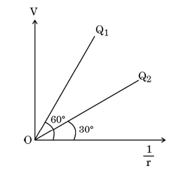
Diagram 1 – CBSE Class 12 PCM Physics 2023 Set 4 Solutions [1 Mark]
Answer: From the case passage, potential V due to a point charge Q varies as V = kQ/r, which means V is directly proportional to Q and inversely proportional to r. The graph shows V varying with 1/r, so the slope of V versus 1/r graph represents k*Q. Therefore, the ratio Q1/Q2 is equal to the ratio of slopes of the lines corresponding to Q1 and Q2 on the graph.
Key Points: Potential V varies as k*Q/r - Plot of V vs 1/r is linear with slope proportional to Q - Ratio Q1/Q2 equals ratio of slopes of their graphs

Section B

Question 3.

Two charges q1 and q2 are placed at the centres of two spherical conducting shells of radius r1 and r2 respectively. The shells are arranged such that their centres are d [ > (r1 + r2)] distance apart. The force on q2 due to q1 is:

[1 Mark]
  • (A) 1/4πε0 q1q2/d2
  • (B) Zero
  • (C) 1/4πε0 q1q2/[d−(r1+r2)]^2
  • (D) 1/4πε0 q1q2/(d−r1)^2
Explanation:

Given the setup:
- Two point charges q1q1 and q2q2 are placed at the centers of two spherical conducting shells with radii r1r1 and r2r2.
- The distance between the centers of the shells is dd where d>(r1+r2)d>(r1+r2).

Since the distance between the centers dd is greater than the sum of the radii of the two shells, the shells do not overlap and the charges can be treated as point charges with respect to each other. This means we can apply Coulomb's law directly to find the force between them.

Coulomb's Law
The force FF between two point charges q1q1 and q2q2 separated by a distance dd is given by:

1/4πε0 q1q2/d2

Question 4. An electron enters a uniform magnetic field with speed v. It describes a semicircular path and comes out of the field. The final speed of the electron is:
[1 Mark]
  • (A) Zero
  • (B) v
  • (C) 2v
  • (D) 2v
Explanation: The final speed of the electron is v because the magnetic field exerts a force that changes the direction of the electron but does not change its speed. As it travels through the magnetic field, the kinetic energy remains constant, indicating that the speed remains the same when it exits the field.
Question 5.

The magnetic field lines near a substance are as shown in the figure. The substance is:
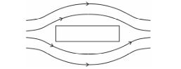
[1 Mark] Diagram 2 – CBSE Class 12 PCM Physics 2023 Set 4 Solutions
  • (A) Iron
  • (B) Copper
  • (C) Sodium
  • (D) Aluminium
Explanation:

To determine the substance based on the magnetic field lines, we need to identify the type of material that exhibits the given magnetic field pattern. The field lines shown indicate that the substance is ferromagnetic, which means it is likely to be iron.

Question 6.

The figure shows variation of current (I) with time (t) in four devices P, Q, R and S. The device in which an alternating current flows is:
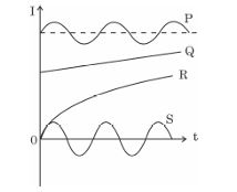
[1 Mark] Diagram 3 – CBSE Class 12 PCM Physics 2023 Set 4 Solutions
  • (A) Q
  • (B) S
  • (C) P
  • (D) R
Explanation:

The device that exhibits a current that varies in both directions over time is identified as an alternating current (AC) device. Usually, this would be represented by a sine wave or a similar varying current pattern, which is characteristic of alternating current. In the options provided, P, whichever displays this characteristic alternating pattern, would be the correct answer.

Question 7. The electromagnetic waves used in radar systems are:
[1 Mark]
  • (A) Infrared waves
  • (B) Ultraviolet rays
  • (C) X-rays
  • (D) Microwaves
Explanation: The correct answer is Microwaves. Radar systems operate primarily in the microwave range of the electromagnetic spectrum, typically between 1 GHz and 100 GHz, because microwaves are effective for long-range detection and can penetrate atmospheric conditions like rain and fog.
Question 8.

In a Young's double slit experiment, the fringe width is found to be β. If the entire apparatus is immersed in a liquid of refractive index μ, the new fringe width will be:

[1 Mark]
  • (A) β/μ
  • (B) β
  • (C) β/μ^2
  • (D) μβ
Explanation: When the entire apparatus is immersed in a liquid of refractive index μ, the fringe width is adjusted by the refractive index since the speed of light in the medium changes. The new fringe width becomes β/μ because the wavelength of light in the medium is reduced by a factor of μ. Thus, the correct answer is β/μ.
Question 9. Photons of energy 3·2 eV are incident on a photosensitive surface. If the stopping potential for the emitted electrons is 1·5 V, the work function for the surface is:
[1 Mark]
  • (A) 1·5 eV
  • (B) 4·7 eV
  • (C) 3·2 eV
  • (D) 1·7 eV
Explanation: The work function (φ) can be calculated using the equation: φ = Energy of photons - Stopping potential. Here, φ = 3.2 eV - 1.5 V = 1.7 eV. Thus, the correct answer is 1.7 eV.
Question 10.

Which of the following statements is not true for nuclear forces?

[1 Mark]
  • (A) They are stronger than Coulomb forces.
  • (B) They saturate as the separation between two nucleons increases.
  • (C) They are always attractive.
  • (D) They have about the same magnitude for different pairs of nucleons.
Explanation:

The statement 'They saturate as the separation between two nucleons increases.' is not true for nuclear forces. Nuclear forces do not exhibit saturation with increasing distance between nucleons, meaning they can have significant effects even at larger separations, unlike other forces such as the electromagnetic force, which diminish over distance.

Question 11.

The direction of induced current in the loop abc is:
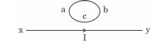
[1 Mark] Diagram 4 – CBSE Class 12 PCM Physics 2023 Set 4 Solutions
  • (A) along acb if I increases
  • (B) along abc if I increases
  • (C) along abc if I is constant
  • (D) along abc if I decreases
Explanation: The correct answer is 'along abc if I decreases'. According to Faraday's law of electromagnetic induction, the induced current will flow in a direction that opposes the change in magnetic flux. If the current I decreases, the magnetic field associated with it also decreases, leading to an induced current that flows in the same direction as the original current to oppose the reduction.
Question 12.

An ac voltage v = v0 sinωt is applied to a series combination of a resistor R and an element X. The instantaneous current in the circuit is I = I0 sin (ωt + π/4). Then which of the following is correct?

[1 Mark]
  • (A) X is a capacitor and XC = R
  • (B) X is an inductor and XL = R
  • (C) X is a capacitor and XC = √2R
  • (D) X is an inductor and XL = √2R
Explanation:

The phase difference between the voltage and current is π/4, indicating that the circuit is inductive; thus, X is an inductor. The relationship between the inductive reactance (XL) and resistance (R) can be derived from the phase angle: tan(π/4) = R / XL, leading to XL = R. Hence, the correct answer is 'X is an inductor and XL = R.'

Question 13.

Assertion (A): When three electric bulbs of power 200 W, 100 W and 50 W are connected in series to a source, the power consumed by the 50 W bulb is maximum.

Reason (R): In a series circuit, current is the same through each bulb, but the potential difference across each bulb is different.

[1 Mark]
  • (A) Assertion (A) is true, but Reason (R) is false.
  • (B) Both Assertion (A) and Reason (R) are true and Reason (R) is the correct explanation of the Assertion (A).
  • (C) Both Assertion (A) and Reason (R) are false.
  • (D) Both Assertion (A) and Reason (R) are true, but Reason (R) is not the correct explanation of the Assertion (A).
Explanation:

Assertion (A) is true because, in a series circuit, the bulb with the lowest power rating (50 W in this case) actually consumes the least power, not the maximum. Reason (R) is true because, in a series circuit, the current is the same through all components, but the voltage drop across each bulb varies depending on its resistance. Therefore, the correct option is Both Assertion (A) and Reason (R) are true and Reason (R) is the correct explanation of the Assertion (A).

Question 14.

Assertion (A): A current carrying square loop made of a wire of length L is placed in a magnetic field. It experiences a torque which is greater than the torque on a circular loop made of the same wire carrying the same current in the same magnetic field.

Reason (R): A square loop occupies more area than a circular loop, both made of wire of the same length.

[1 Mark]
  • (A) Assertion (A) is true, but Reason (R) is false.
  • (B) Both Assertion (A) and Reason (R) are true, but Reason (R) is not the correct explanation of the Assertion (A).
  • (C) Both Assertion (A) and Reason (R) are true and Reason (R) is the correct explanation of the Assertion (A).
  • (D) Both Assertion (A) and Reason (R) are false.
Explanation:

Both Assertion (A) and Reason (R) are true, but Reason (R) is the correct explanation of the Assertion (A). A square loop does not necessarily experience greater torque than a circular loop just because it occupies more area; the torque depends on the configuration and orientation of the loop in the magnetic field, not merely on the area alone.

Question 15.

A plane wavefront is incident on a concave mirror of radius of curvature R. The radius of the refracted wavefront will be :

[1 Mark]
  • (A) 2R
  • (B) R/2
  • (C) R
  • (D) R/4
Explanation: When a plane wavefront strikes a concave mirror, it can be treated as if it converges to the focus of the mirror. The radius of curvature R relates to the focal length f of the mirror by the equation f = R/2. Therefore, the radius of the refracted wavefront, which is the distance from the focus to the point of reflection (the center of the wavefront), will be equal to 2f. Thus, the radius of the refracted wavefront will be 2R.
Question 16.

A proton and an alpha particle have the same kinetic energy. The ratio of de Broglie wavelengths associated with the proton to that with the alpha particle is :

[1 Mark]
  • (A) 2√2
  • (B) 1
  • (C) 2
  • (D) 1/2
Explanation:

The de Broglie wavelength (λ) is given by the formula λ = h/p, where h is Planck's constant and p is momentum. Since both particles have the same kinetic energy (K.E.), we can derive their momentum using the relation K.E. = p²/(2m). For the proton (mass m_p) and the alpha particle (mass m_α), we can express the momentum as p_p = √(2m_p * K.E.) and p_α = √(2m_α * K.E.). Therefore, the ratio of their wavelengths is λ_p/λ_α = (h/p_p) / (h/p_α) = p_α/p_p = sqrt(m_p/m_α). Given that the mass of an alpha particle is four times that of a proton (m_α = 4m_p), we find λ_p/λ_α = √(m_p/(4m_p)) = 1/2. Thus, the correct option is 1/2.

Question 17.

The potential energy of an electron in the second excited state in hydrogen atom is :

[1 Mark]
  • (A) - 6.8 eV
  • (B) -1.51 eV
  • (C) -3.4 eV
  • (D) -3.02 eV
Explanation:

The energy levels of an electron in a hydrogen atom are given by the formula E_n = -13.6 eV/n², where n is the principal quantum number. For the second excited state, n = 3. Therefore, E_3 = -13.6 eV / (3²) = -13.6 eV / 9 = -1.51 eV. Thus, the correct option is -1.51 eV.

Question 18.

The difference in mass of 7X nucleus and total mass of its constituent nucleons is 21·00 u. The binding energy per nucleon for this nucleus is equal to the energy equivalent of :

[1 Mark]
  • (A) 3u
  • (B) 3.5u
  • (C) 7u
  • (D) 21u
Explanation: The binding energy of a nucleus is given by the mass difference between the nucleons and the nucleus, converted to energy using Einstein's equation E=mc^2. The given mass difference is 21.00 u, and since there are 7 nucleons, the binding energy per nucleon is 21.00 u / 7 = 3.00 u. Therefore, the correct option is 3u.
Question 19.

The threshold voltage for a p-n junction diode used in the circuit is 0·7 V. The type of biasing and current in the circuit are :
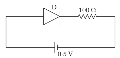
[1 Mark] Diagram 5 – CBSE Class 12 PCM Physics 2023 Set 4 Solutions
  • (A) Reverse biasing, 0 A
  • (B) Forward biasing, 0 A
  • (C) Reverse biasing, 2 mA
  • (D) Forward biasing, 5 mA
Explanation:

The correct answer is 'Forward biasing, 5 mA'. In forward biasing, the p-side is connected to the positive terminal of the voltage source and the n-side to the negative terminal. This setup allows current to flow through the diode after the threshold voltage of 0.7 V is reached. Therefore, a current of 5 mA indicates that the diode is conducting in the forward direction.

Question 20.

Assertion (A) : In 'n' type semiconductor, number density of electron is greater than the number density of holes but the crystal maintains an overall charge neutrality.

Reason (R) : The charge of electrons donated by donor atoms is just equal and opposite to that of the ionised donor.

[1 Mark]
  • (A) Assertion (A) is true, but Reason (R) is false.
  • (B) Assertion (A) is false and Reason (R) is also false.
  • (C) Both Assertion (A) and Reason (R) are true, but Reason (R) is not the correct explanation of the Assertion (A).
  • (D) Both Assertion (A) and Reason (R) are true and Reason (R) is the correct explanation of the Assertion (A).
Explanation: Both Assertion (A) and Reason (R) are true and Reason (R) is the correct explanation of the Assertion (A). In 'n' type semiconductors, electrons are added by donor atoms which outnumber the holes, but the overall charge remains balanced due to the equal and opposite charge of the ionized donor atoms.

Section C

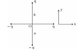
Question 21. Two identical dipoles are arranged in the x-y plane as shown in the figure. Find the magnitude and the direction of the net electric field at the origin O.
[2 Marks] Diagram 6 – CBSE Class 12 PCM Physics 2023 Set 4 Solutions
Answer: To find the net electric field at the origin O due to the two identical dipoles, we use the formula for the electric field due to a dipole. Since the dipoles are identical and symmetrically arranged, their fields at point O will have equal magnitude but opposite direction along the dipole axis. Thus, they will cancel each other out completely, resulting in a net electric field of zero at the origin.
Key Points: Electric field due to dipole formula - Identical dipoles - Symmetrical arrangement - Opposite directions - Net electric field is zero
Question 22. Write two differences between the emf and terminal potential difference of a cell. What is the most important precaution that one should take while drawing current from a cell?
[2 Marks]
Answer: The electromotive force (emf) of a cell is the maximum potential difference it can provide when no current flows, while the terminal potential difference is the actual voltage available when a current is drawn. The emf remains constant regardless of load, whereas the terminal potential difference decreases with increasing load due to internal resistance. A crucial precaution while drawing current is to avoid drawing excessive current, which can lead to overheating and damage to the cell.
Key Points: Difference 1: EMF is maximum potential, Terminal PD is actual voltage; Difference 2: EMF remains constant, Terminal PD decreases with load; Precaution: Avoid excessive current draw to prevent damage.
Question 23.

What is a displacement current? How is it different from a conduction current?

[2 Marks]
Answer: Displacement current is a term introduced by Maxwell, representing the change in electric displacement field in a dielectric medium, especially when there is a time-varying electric field. It accounts for the current that flows in a capacitor during charging or discharging, which allows for continuous current flow in the circuit. In contrast, conduction current involves the flow of charge carriers like electrons through a conductor due to an electric field.
Key Points: Defining displacement current-Conductive vs. displacement current-Microwave applications
Question 24.

a) Obtain an expression for the electrostatic potential energy of a system of three charges q, 2q, and -3q placed at the vertices of an equilateral triangle of side a.

[2 Marks]
Answer: The electrostatic potential energy (U) of a system of point charges is given by the formula U = k * Σ(qi * qj / rij), summing over all unique pairs of charges. For three charges q, 2q, and -3q at vertices of an equilateral triangle with side a, U becomes U = k * [ (q * 2q / a) + (q * -3q / a) + (2q * -3q / a) ]. After substitution and simplification, we find U = k * (2q^2 / a - 3q^2 / a - 6q^2 / a) = -7kq^2 / a.
Key Points: Electrostatic potential energy formula, Pairwise interaction, Equilateral triangle geometry, Final expression for U
Question 25.

A small magnetised needle P is placed at the origin of x-y plane with its magnetic moment pointing along the y-axis. Another identical magnetised needle Q is placed in two positions, one by one.

Case 1 : at (a, 0) with its magnetic moment pointing along x-axis.

Case 2 : at (0, a) with its magnetic moment pointing along y-axis.

(a) In which case is the potential energy of P and Q minimum ?

(b) In which case is P and Q not in equilibrium ?

Justify your answers.

[2 Marks]
Answer: The potential energy is minimum in Case 1 when Q is placed at (a, 0) with its moment along the x-axis, as the moment of Q is perpendicular to P, leading to stable equilibrium. In Case 2, when Q is at (0, a), both P and Q have their moments aligned, resulting in maximum potential energy and instability. Hence, P and Q are not in equilibrium in Case 2.
Key Points: Case 1 has minimum potential energy; Case 2 has maximum potential energy; Maximum potential indicates instability.
Question 26.

The figure shows v^2_m versus 1/λ graph for photoelectrons emitted from a surface where Vm is the maximum speed of electrons and λ is the wavelength of incident radiation. Using this graph and Einstein's photoelectric equation, obtain the expression for Planck's constant and work function of the surface.
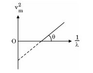
[2 Marks] Diagram 7 – CBSE Class 12 PCM Physics 2023 Set 4 Solutions
Answer: From Einstein's photoelectric equation, we have E = hν = ϕ + rac{1}{2}mVM^2, where E is the energy of photons, ϕ is the work function, and VM is the maximum speed. The graph of v^2_m versus 1/λ is linear, suggesting v^2_m = m(h/λ - ϕ). The slope of this line gives m(h) and the intercept provides ϕ. Thus, Planck's constant h and work function ϕ can be derived from the slope and intercept respectively.
Key Points: Einstein's photoelectric equation, relationship between frequency and wavelength, linear relationship in graph, slope provides Planck's constant, intercept gives work function
Question 27.

Draw the graph showing the variation of binding energy per nucleon with mass number A of nuclei (2 < A < 170). Use this graph to explain the release of energy in nuclear fission.

[2 Marks]
Answer: The graph of binding energy per nucleon versus mass number A shows a rising trend up to iron (A ≈ 56), where the binding energy is maximized. As A increases past iron, the binding energy per nucleon begins to decrease. This indicates that elements heavier than iron, when split (nuclear fission), release energy because their binding energy per nucleon is lower compared to the products formed. Thus, energy is released during fission.
Key Points: Graph depicts binding energy trends; Maximum binding energy around iron; Fission releases energy; Heavy nuclei have lower binding energy.
Question 28.

Write any two characteristics of an electromagnetic wave. Why are microwaves used in radar systems?

[2 Marks]
Answer: Two characteristics of electromagnetic waves include their ability to travel at the speed of light and their capacity to carry energy across distances. Microwaves, which are a type of electromagnetic wave with short wavelengths, are used in radar systems because they can efficiently interact with materials and are suitable for precise measurements, such as aircraft navigation and speed detection for various objects. Their short wavelength allows for better resolution in radar technology.
Key Points: Ability to travel at the speed of light-Can carry energy across distances-Short wavelengths suitable for radar systems-Effective interaction with materials-Used in aircraft navigation and speed detection
Question 29.

b) Two small conducting balls A and B of radius r1 and r2 have charges q1 and q2 respectively. They are connected by a wire. Obtain the expression for charges on A and B in equilibrium.

[2 Marks]
Answer: When two conducting balls A and B with radii r1 and r2, having initial charges q1 and q2, are connected by a wire, charges will redistribute until they reach the same electric potential. The potential V of a sphere is given by V = k * Q/r, where k is a constant. In equilibrium, VA = VB, which leads to k*q1/r1 = k*q2/r2. Hence, the charges are given by q1 = (r1/(r1+r2)) * (q1 + q2) and q2 = (r2/(r1+r2)) * (q1 + q2).
Key Points: Charge redistribution-electric potential-equality of potentials

Section D

Question 30. Two circular loops A and B, each of radius 3 m, are placed coaxially at a distance of 4 m. They carry currents of 3 A and 2 A in opposite directions respectively. Find the net magnetic field at the centre of loop A.
[3 Marks]
Answer: To calculate the net magnetic field at the center of loop A, we will first calculate the field produced by each loop using the formula for the magnetic field due to a loop at its center: B = (μ₀ * I) / (2 * R). For loop A, I = 3 A and R = 3 m, thus BA = (4π × 10^-7 T m/A * 3 A) / (2 * 3 m) = 2 × 10^-7 T. For loop B, which is 1 m away (distance = 4 m - 3 m), I = 2 A, thus BB = (4π × 10^-7 * 2 A) / (2 * 4 m) = 1.57 × 10^-7 T. Both currents are in opposite directions, so the net field is BA - BB = 2 × 10^-7 - 1.57 × 10^-7 = 0.43 × 10^-7 T. Hence, the net magnetic field at the center of loop A is 0.43 × 10^-7 T in the direction of the current in loop A.
Key Points: Calculate magnetic field for loop A; Use formula B = (μ₀ * I) / (2 * R); Account for distance of loop B affecting its field.
Question 31. Briefly explain the Geiger-Marsden experiment. Show the variation of the number of particles scattered (N) with scattering angle (θ) in this experiment. What is the main conclusion that can be inferred from this plot?
[3 Marks]
Answer: The Geiger-Marsden experiment, conducted in 1909, aimed to probe the structure of the atom. In this experiment, a beam of alpha particles was directed at a thin gold foil, and detectors recorded the scattering of these particles. Most alpha particles passed through the foil with little deflection, but some were deflected at large angles. The variation of the number of particles scattered (N) with scattering angle (θ) shows that as θ increases, N decreases sharply, indicating that most of the mass of the atom is concentrated in a small nucleus. The key conclusion is that the atom consists of a dense, positively charged nucleus surrounded by a cloud of electrons, challenging the previous plum pudding model.
Key Points: 1. Purpose of the experiment was to investigate atomic structure. 2. Most alpha particles passed through, few deflected significantly. 3. N decreases with increasing θ, revealing atomic nucleus presence. 4. Main conclusion: atom has a small, dense nucleus, contradicting the plum pudding model.
Question 32.

(a) The figure shows the variation of induced emf as a function of rate of change of current for two identical solenoids X and Y. One is air cored and the other is iron cored. Which one of them is iron cored ? Why ?

(b) Obtain an expression for self-inductance of a long solenoid of length L and cross-sectional area A having N turns.
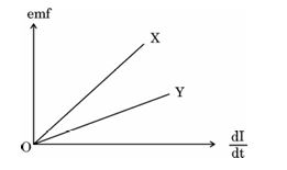
[3 Marks] Diagram 8 – CBSE Class 12 PCM Physics 2023 Set 4 Solutions
Answer: To determine which solenoid, X or Y, is iron cored, we look at the variation of induced emf with the rate of change of current. The iron cored solenoid has a higher induced emf for the same rate of change of current compared to the air cored solenoid. This is due to the higher magnetic permeability of iron, which enhances the magnetic field and hence the induced emf. For part (b), the self-inductance L of a long solenoid can be expressed with the formula L = (μ₀N²A)/L, where μ₀ is the permeability of free space, N is the number of turns, A is the cross-sectional area, and L is the length of the solenoid.
Key Points: 1. Compare induced emf for solenoids X and Y. 2. Higher emf indicates iron core due to material's magnetic permeability. 3. Self-inductance derived from basic formulas relating permeability, turns, area, and length.
Question 33.

(a) A resistor of 30 ohm and a capacitor of 250/π μF are connected in series to a 200 V, 50 Hz ac source. Calculate (i) the current in the circuit, and (ii) voltage drops across the resistor and the capacitor. (iii) Is the algebraic sum of these voltages more than the source voltage ? If yes, solve the paradox.

[3 Marks]
Answer: For part (a), we first find the capacitive reactance (Xc = 1/(2πfC)). Given C = 250/π μF and f = 50 Hz, we calculate Xc ≈ 12.73 ohms. The total impedance (Z) in the circuit is Z = √(R² + Xc²) = √(30² + 12.73²) ≈ 33.15 ohms. The current (I) can be calculated using Ohm's law: I = V/Z = 200/33.15 ≈ 6.02 A. The voltage drop across the resistor (Vr = I*R ≈ 180.6 V) and capacitor (Vc = I*Xc ≈ 76.63 V). Algebraically, Vr + Vc ≠ V_source, indicating a phase difference rather than a paradox.
Key Points: Calculating capacitive reactance (Xc); finding total impedance (Z); using Ohm's law to determine the current (I); voltage drop across resistor (Vr); voltage drop across capacitor (Vc); understanding phase difference in AC circuits.
Question 34.

(b) (i) In a Young's double-slit experiment SS2-SS1 = λ/4 , where S1 and S2 are the two slits as shown in the figure. Find the path difference (S2P -S1P) for constructive and destructive interference at P.

(ii) What is the effect on the interference fringes in a Young's double-slit experiment, if the monochromatic source S is replaced by a source of white light ?
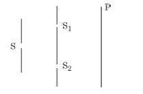
[3 Marks] Diagram 9 – CBSE Class 12 PCM Physics 2023 Set 4 Solutions
Answer: In diffraction, the phase difference (φ) determines the nature of the fringe formed. A phase difference of 5π corresponds to an odd multiple of π, implying destructive interference occurs. Thus, a dark fringe will be observed at the specified point on the screen. For obtaining eight maxima of double-slit patterns within a single-slit central maximum, the slit width 'a' should be designed to allow those maxima while considering both central maximum dispersal and fringe shifts. The calculation involves careful assessment of the relationships between 'a', 'd', and the number of expected maxima.
Key Points: Phase difference of 5π signifies destructive interference; hence a dark fringe forms. Width 'a' must be appropriately calculated for double-slit maxima within single-slit limits; interference conditions must be met for both central maxima.
Question 35.

(b) A series LCR circuit with R = 20 ohm , L = 2 H and C = 50 μF is connected to a 200 volts ac source of variable frequency. What is (i) the amplitude of the current, and (ii) the average power transferred to the circuit in one complete cycle, at resonance ? (iii) Calculate the potential drop across the capacitor.

[3 Marks]
Answer: To find the amplitude of the current at resonance, we use the formula I = V/R, where V = 200 V and R = 20 ohm. Thus, the amplitude of the current I = 200/20 = 10 A. The average power at resonance is given by P = V * I = 200 * 10 = 2000 W. The potential drop across the capacitor is calculated using Vc = I * Xc, where Xc = 1/(ωC). First, we find the resonant frequency: ω = 1/√(LC) = 10 rad/s, giving Xc = 2 ohm. Therefore, Vc = 10 * 2 = 20 V.
Key Points: Amplitude of current I = V/R; Average power P = VI; Xc = 1/(ωC); Resonant frequency ω = 1/√(LC)
Question 36.

(a) (i) In diffraction due to a single slit, the phase difference between light waves reaching a point on the screen is 5π . Explain whether a bright or a dark fringe will be formed at the point.

(ii) What should the width (a) of each slit be to obtain eight maxima of two double-slit patterns (slit separation d) within the central maximum of the single slit pattern ?

(iii) Draw the plot of intensity distribution in a diffraction pattern due to a single slit.

[3 Marks]
Answer: (i) The phase difference of 5π corresponds to an odd multiple of π, which indicates destructive interference. Thus, a dark fringe will be formed at the point on the screen. (ii) To obtain eight maxima of two double-slit patterns within the central maximum of the single-slit diffraction pattern, the width (a) of each slit can be calculated using the formula: a = λN/d, where λ is the wavelength, N is the number of required maxima, and d is the distance between the slits. This ensures that the maxima fit within the central maximum of the diffraction pattern. (iii) The plot of intensity distribution for a single slit diffraction shows a central bright maximum that decreases in intensity as one moves away from the center, with alternating dark and bright fringes.
Key Points: phase difference of 5π indicates dark fringe, destructive interference; width of each slit given by a=lambda*N/d, ensuring 8 maxima fit in central maximum; intensity distribution shows central bright maximum and decreasing intensity on both sides with alternating patterns

Section E

Question 37.

a) (i) Define mobility of electrons. Give its SI units.

(ii) A steady current flows through a wire AB, as shown in the figure. What happens to the electric field and the drift velocity along the wire? Justify your answer.

(iii) Consider the circuit shown in the figure. Find the effective resistance of the circuit and the current drawn from the battery.
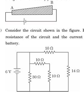
[5 Marks] Diagram 10 – CBSE Class 12 PCM Physics 2023 Set 4 Solutions
Answer: The mobility of electrons, denoted by μ, is defined as the ability of charge carriers, such as electrons, to move through a conductor in response to an electric field. It represents the drift velocity (Vd) per unit electric field (E), mathematically expressed as μ = |Vd| / E. The SI unit of mobility is m²/Vs, which reflects how the drift of electrons varies with the strength of the electric field. In steady conditions, the electric field inside a conductor remains constant, while the drift velocity of electrons also stabilizes, allowing continuous current flow. Total effective resistance in an electrical circuit can be determined by using Ohm's Law (R = V/I) alongside series and parallel resistance formulas, based on the configuration of the circuit.
Key Points: 1. Mobility definition: mobility is the ratio of drift velocity to electric field. 2. SI unit of mobility: m²/Vs. 3. In a steady current, electric field remains constant and drift velocity stabilizes, leading to continuous current flow. 4. Effective resistance calculation using Ohm's Law and circuit configuration.
Question 38.

(a) (i) Draw a ray diagram to show how the final image is formed at infinity in an astronomical refracting telescope. Obtain an expression for its magnifying power.

(ii) Two thin lenses L₁ and L₂, L₁ being a convex lens of focal length 24 cm and L₂ a concave lens of focal length 18 cm are placed coaxially at a separation of 45 cm. A 1 cm tall object is placed in front of the lens L₁ at a distance of 36 cm. Find the location and height of the image formed by the combination.

[5 Marks]
Answer: To illustrate the formation of an image at infinity with an astronomical refracting telescope, we begin with the objective lens (L₁) and eyepiece lens (L₂). The telescope uses a convex lens as the objective, focusing parallel rays from a distant object to a point called the focal point, forming a real and inverted image. This image acts as a virtual object for the eyepiece, which is a concave lens, allowing the final image to be formed at infinity, enhancing magnification. The magnifying power is given by the formula m = (L/f₀)(L/fₑ), where L is the length of the telescope, f₀ is the focal length of the objective lens, and fₑ is the focal length of the eyepiece lens.

For the second part, with lenses L₁ (focal length 24 cm) and L₂ (focal length -18 cm) arranged at 45 cm distance: First, we find the image formed by L₁. The object distance is u₁ = -36 cm. Using the lens formula 1/f = 1/v + 1/u, we calculate v₁. The first image distance v₁ from L₁ would be 72 cm, forming a real image. This image acts as the object for L₂, and we can find the height of the final image using magnification.
Key Points: Ray diagram showing parallel rays from distant object to focus of L₁; L₂ forms image at infinity; Formula for magnifying power m = (L/f₀)(L/fₑ); Given L₁ and L₂ focal lengths and separations; Calculation of image distances using lens formula; Step to find height of final image using lens magnification.
Question 39.

a) (i) A germanium crystal is doped with antimony. With the help of an energy-band diagram, explain how the conductivity of the doped crystal is affected.

(ii) Briefly explain the two processes involved in the formation of a p-n junction.

(iii) What will the effect of (1) forward biasing, and (2) reverse biasing be on the width of depletion layer in a p-n junction diode?

[5 Marks]
Answer: When a germanium crystal is doped with antimony, it introduces extra electrons, making it an n-type semiconductor. The energy-band diagram shows that the conduction band of germanium shifts upwards due to the additional energy levels from antimony, reducing the energy gap between the conduction and valence bands and increasing conductivity. In a p-n junction, formed by bringing p-type and n-type materials together, holes and electrons recombine, creating a depletion region. Forward biasing narrows the depletion layer, allowing current to flow easily, while reverse biasing widens the depletion layer, restricting current flow. The full-wave rectifier converts both halves of AC input into DC using two diodes, allowing current during both cycles. Diode V-I characteristics show a forward voltage drop and a high resistance in reverse, making them effective for rectification. Silicon behaves as a semiconductor due to its four valence electrons, allowing controlled conduction, whereas carbon's bonding leads to insulating behavior due to its distinct orbital overlap.
Key Points: 1. Doping germanium with antimony creates n-type semiconductor due to extra electrons; 2. Energy-band diagram illustrates reduced energy gap, enhancing conductivity; 3. Formation of p-n junction involves diffusion and electric field establishment; 4. Forward bias narrows depletion layer, reverse bias widens it; 5. Full-wave rectifier uses two diodes to convert AC to DC; 6. V-I characteristics of diodes exhibit forward conduction and reverse blocking; 7. Silicon is a semiconductor due to valence electron structure, while carbon acts as an insulator.
Question 40.

(b) (i) Define electrical conductivity of a wire. Give its SI unit.

(ii) High current is to be drawn safely from (1) a low-voltage battery, and (2) a high-voltage battery. What can you say about the internal resistance of the two batteries ?

(iii) Calculate the total energy supplied by the batteries to the circuit shown in the figure, in one minute.
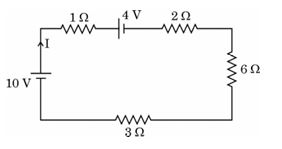
[5 Marks] Diagram 11 – CBSE Class 12 PCM Physics 2023 Set 4 Solutions
Answer: Electrical conductivity is a measure of a material's ability to conduct electric current. It is defined as the ratio of the current density to the electric field strength in the material, indicating how easily the charge carriers move through the conductor. The SI unit of electrical conductivity is siemens per meter (S/m).
For a low-voltage battery, the internal resistance tends to be lower to facilitate high current flow, ensuring efficiency. Conversely, a high-voltage battery generally has a higher internal resistance to manage the increased voltage without risking short circuits, which may limit the current.
To calculate the total energy supplied by the batteries, we use the formula Energy (E) = Power (P) × Time (t), where Power can be calculated using P = Voltage (V) × Current (I). Assuming a voltage and current are specified, and time is one minute (60 seconds), we can find the overall energy output successfully.
Key Points: Electrical conductivity definition; SI unit is S/m; Low-voltage battery has lower internal resistance; High-voltage battery has higher internal resistance; Total energy calculation: E = P × t, P = V × I; Time considered is one minute.
Question 41.

(b) (i) Explain the working principle of an optical fibre with the help of a diagram. Mention one use of a light pipe.

(ii) A ray of light is incident at an angle of 60 degree on one face of a prism with the prism angle A = 60 degree. The ray passes symmetrically through the prism. Find the angle of minimum deviation ( δm) and refractive index of the material of the prism. If the prism is immersed in water, how will δm be affected ? Justify your answer.

[5 Marks]
Answer: An optical fibre operates on the principle of total internal reflection. It consists of a core (higher refractive index) surrounded by a cladding (lower refractive index). When light enters the core at an angle greater than the critical angle, it reflects internally, allowing light to travel through bends without loss. A diagram would show the light's path reflecting along the core. One common use of a light pipe is in medical instruments, such as endoscopes, which enable visualization inside the body without invasive procedures.

For the prism, when a ray of light incident at 60° hits a prism with A = 60°, it will pass symmetrically through it. The minimum deviation δmδ_m can be calculated using the formula δm=i+e−Aδ_m = i + e - A, where ii is the angle of incidence and ee is the angle of emergence, both equal in this case, resulting in δm=60°+60°−60°=60°δ_m = 60° + 60° - 60° = 60°. The refractive index n is given by n=sin⁡((A+δm)/2)sin⁡(A/2)n = \frac{\sin((A + δ_m)/2)}{\sin(A/2)}, resulting in an n value around 1.732. When the prism is immersed in water, the refractive index decreases, leading to an increase in δmδ_m due to the reduced light bending ability.
Key Points: Principle of total internal reflection in optical fibres; Core and cladding structure; Internal light reflection; Diagram showing light path; Use of optical fibres in endoscopes; Calculation of minimum deviation using prism formula; Symmetrical light path through prism; Refractive index calculation; Effect of water immersion on minimum deviation.
Question 42.

(b) (i) With the help of a circuit diagram, briefly explain the working of a full-wave rectifier using p-n junction diodes.

(ii) Draw V- I characteristics of a p-n junction diode. Explain how these characteristics make a diode suitable for rectification.

(iii) Carbon and silicon have the same lattice structure. Then why is carbon an insulator but silicon a semiconductor ?

[5 Marks]
Answer: A full-wave rectifier converts alternating current (AC) to direct current (DC) using two p-n junction diodes arranged in a bridge configuration. During the positive half-cycle of AC, diodes D1 and D2 conduct, allowing current to pass through the load. During the negative half-cycle, diodes D3 and D4 conduct, again allowing current to flow in the same direction through the load. Hence, both halves of the AC waveform contribute to output DC. The V-I characteristics of a p-n junction diode show it conducts when forward-biased (positive voltage) and blocks reverse current (negative voltage). This behavior is essential for rectification. Silicon, despite having a similar lattice structure to carbon, acts as a semiconductor because of its ability to conduct electricity under certain conditions, particularly when doped, while carbon remains an insulator due to its limited free charge carriers.
Key Points: Working principle of a full-wave rectifier; Circuit diagram with two diodes; Operation during positive and negative cycles; V-I characteristics showing conduction and blocking; Explanation of silicon as a semiconductor due to free carriers vs. carbon.

Paper Details

CBSE Board Exam 2023

Class

Class 12 PCM

Subject

Physics

Year

2023

Set

Set 4

Other Years — Physics

2022 Set-1

2022 Set-2

2022 Set-3

2022 Set-4

2023 Set-1

2023 Set-2

2023 Set-3

2023 Set-4

2023 Set-5

2024 Set-1

2024 Set-2

2024 Set-3

2024 Set-4

2024 Set-5

2025 Set-1

2025 Set-2

2025 Set-4

2025 Set-5

2025 Set-6

2025 Set-7

CBSE Class 12 Physics 2023 Set 4 Solutions | Prepzy