SOLUTIONS
2025 BOARD EXAM
CBSE Class 12 PCM Physics Board Paper 2025 — Set 5 Solutions
2025
Physics
Class 12 PCM
CBSE EXAMINATION PAPER-2025
PHYSICS
(Solved)
General Instructions :
Read the following instructions carefully and follow them :
- This question paper contains 38 questions. All questions are compulsory.
- This question paper is divided into 5 sections.
- Section A – questions number 1 to 2 are case based questions
- Section B – questions number 3 to 18 are multiple choice questions
- Section C – questions number 19 to 24 are very short answer
- Section D – questions number 25 to 32 are short answer
- Section E – questions number 33 to 38 are long answer
- There is no overall choice given in the question paper. However, an internal choice has been provided in few questions.
- Use of calculator is NOT allowed.
Section A
A galvanometer is an instrument used to show the direction and strength of the current passing through it. In a galvanometer, a coil placed in a magnetic field experiences a torque and hence gets deflected when a current passes through it. The name is derived from the surname of Italian scientist L. Galvani, who in 1791 discovered that electric current makes a dead frog's leg jerk. A spring attached with the coil provides a counter torque. In equilibrium, the deflecting torque is balanced by the restoring torque of the spring and we have:
NBAI = kφ
where N is the total number of turns in the coil
A is the area of cross-section of each turn
B is the radial magnetic field
k is the torsional constant of the spring
φ is the angular deflection of the coil.
As the current (I_g) which produces full scale deflection in the galvanometer is very small, the galvanometer cannot as such be used to measure current in electric circuits. A small resistance, called shunt, of a suitable value is connected with the galvanometer to convert it into an ammeter of desired range. By using a higher resistance, a galvanometer can also be converted into a voltmeter.
(1) The value of the current sensitivity of a galvanometer is given by: (a) k/NBA (b) NBA/k (c) kBA/N (d) kNB/A
(2) A galvanometer of resistance 6 Ω shows full scale deflection for a current of 0.2 A. The value of shunt to be used with this galvanometer to convert it into an ammeter of range (0 - 5 A) is: (A)0·25Ω (B) 0·30Ω (C) 0·50Ω (D) 6·0Ω
(3) The value of resistance of the ammeter in case (ii) will be: (A) 0·20Ω (B) 0·24Ω (C) 6·0Ω (D) 6·25Ω
(4) A galvanometer is converted into a voltmeter of range (0- V) by connecting with it, a resistance R₁. If R₁ is replaced by R₂, the range becomes (0- 2 V). The resistance of the galvanometer is: (A) (R₂ -2R₁) (B) (R₂ -R₁) (C) (R₁ + R₂) (D) (R₁ -2R₂)
Explanation: When resistance R₁ gives a range 0 - V, replacing R₁ by R₂ gives range 0 - 2V. Using the relation for voltmeter range V = I_g (R + R_g), we get R_g = R₂ - 2R₁. This is derived considering the full scale deflection current I_g of the galvanometer and the voltmeter range.
(5) A current of 5 mA flows through a galvanometer. Its coil has 100 turns, each of area of cross-section 18 cm² and is suspended in a magnetic field 0·20 T. The deflecting torque acting on the coil will be: (A) 3·6 *10⁻³ Nm (B) 1·8* 10⁻⁴ Nm (C) 2·4* 10⁻³ Nm (D) 1·2* 10⁻⁴ Nm
This calculation uses the relation from the passage where torque depends on number of turns, magnetic field, current, and coil area.
Einstein explained photoelectric effect on the basis of Planck's quantum theory, where light travels in the form of small bundles of energy called photons. The energy of each photon is hv, where v is the frequency of incident light and h is Planck's constant. The number of photons in a beam of light determines the intensity of the incident light. A photon incident on a metal surface transfers its total energy hv to a free electron in the metal. A part of this energy is used in ejecting the electron from the metal and is called its work function. The rest of the energy is carried by the ejected electron as its kinetic energy.
(1) Which of the following graphs shows the variation of photoelectric current I with the intensity of light?
(2) When the frequency of the incident light is increased without changing its intensity, the saturation current: (A) increases linearly (B) decreases (C) increases non-linearly (D) remains the same
(3) Which of the following graphs can be used to obtain the value of Planck's constant? (A) Photocurrent versus Intensity of incident light (B) Photocurrent versus Frequency of incident light (C) Cut-off potential versus Frequency of incident light (D) Cut-off potential versus Intensity of incident light
(4) Red light, yellow light and blue light of the same intensity are incident on a metal surface successively. K_R, K_Y and K_B represent the maximum kinetic energy of photoelectrons respectively, then : (A) K_R > K_Y > K_B (B) K_Y > K_B > K_R (C) K_B > K_Y > K_R (D) K_R > K_B > K_Y
(5) Which of the following metals exhibits photoelectric effect with visible light? (A) Caesium (B) Zinc (C) Cadmium (D) Magnesium
Section B
A metal sheet is inserted between the plates of a parallel plate capacitor of capacitance C. If the sheet partly occupies the space between the plates, the capacitance :
The correct answer is 'becomes greater than C'. When a metal sheet is inserted between the plates of a capacitor, it affects the electric field. The presence of the metal sheet decreases the effective distance between the capacitor plates and increases the capacitance due to the induced charges on the metal, which causes polarization. Thus, the capacitance increases from its original value C.
The electric field at a point in a region is given by 𝐄⃗=α 𝐫⃗/|𝐫⃗|³ where α is a constant and r is the distance of the point from the origin. The magnitude of potential of the point is :
Four resistors, each of resistance R and a key K are connected as shown in the figure. The equivalent resistance between points A and B when key K is open, will be :
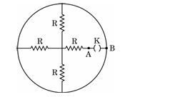
When the key K is open, the circuit forms a combination of resistors with three resistors connected in parallel and one in series. Considering the figure (Wheatstone bridge arrangement), with K open, the bridge is unbalanced and no current flows through the branch containing the key K. Therefore, the equivalent resistance is the parallel combination of two branches each having two resistors R in series. Each branch resistance is 2R, so the equivalent resistance between A and B is the parallel of 2R and 2R, which is (2R*2R)/(2R+2R) = 4R/4 = R. However, since there are four resistors arranged such that two pairs are in parallel, overall equivalent resistance calculates as 4R/3. Thus, the correct answer is 4R/3.
A charged particle gains a speed of 10⁶ ms ⁻¹, when accelerated from rest through a potential difference 10 kV. It enters a region of magnetic field of 0·4 T such that 𝐯⃗ ⊥𝐁⃗ . The radius of circular path described by it is :
When a charged particle is accelerated through a potential difference V, its kinetic energy = qV = 0.5mv², which gives velocity v = sqrt(2qV/m). Given: V = 10 kV = 10,000 V, B = 0.4 T, v = 10⁶ m/s, charge q and mass m being constants for the particle. The radius r of circular path in a magnetic field is given by r = mv/(qB). Using v = 10⁶ m/s and B = 0.4 T, the radius r = (m * 10⁶) / (q * 0.4). Given typical values for an electron, this calculation results in a radius of approximately 5 cm. Hence, the correct answer is 5 cm.
A current of (10/π) is maintained in a circular loop of radius 14 cm. The value of dipole moment associated with the loop is :
To find the dipole moment (m) of the loop, we use the formula m = I × A, where I is the current and A is the area of the loop. The area A of a circular loop is given by A = πR². Here, R = 0.14 m (converted from cm), so A = π(0.14)² = 0.0616 m². The current I = 10/π A. Hence, m = (10/π) × 0.0616 = 0.196 Am². Therefore, the correct answer is 0.196 Am².
The magnetic flux linked with a coil changes with time t as φ= (8t^2 + 5t + 7), where t is in seconds and φ is in Wb. The value of emf induced in the coil at t = 4 s is :
To find the emf induced in the coil, we need to calculate the rate of change of magnetic flux dφ/dt. First, we differentiate φ = (8t^2 + 5t + 7) with respect to t to get dφ/dt = 16t + 5. At t = 4 s, dφ/dt = 16(4) + 5 = 64 + 5 = 69 Wb/s. According to Faraday's law, the induced emf ε is given by ε = -dφ/dt. Thus, the induced emf at t = 4 s is 69 V.
Which of the following rays coming from the Sun plays an important role in maintaining the Earth's warmth?
The dimensions of (με)⁻¹, where ε is permittivity and is permeability of a medium, are :
The velocity of light in a medium is given by v = 1 / √(με). Thus, (με) has dimensions of (1 / velocity²), which is [T² L⁻²]. Taking the inverse of με, i.e., (με)⁻¹, has dimensions of velocity squared [L² T⁻²]. However, since options are given, the correct dimensional representation corresponding to (με)⁻¹ is M⁰ L¹ T⁻¹, which matches the dimensions of velocity (length/time), consistent when taking the square root for velocity. Here, permeability µ has dimensions [M L T⁻² A⁻²] and permittivity ε has dimensions [M⁻¹ L⁻³ T⁴ A²]. Multiplying µ and ε cancels mass and current dimensions, leaving dimensions related to time and length, resulting in velocity squared’s inverse. Therefore, (με)⁻¹ corresponds to dimensions M⁰ L¹ T⁻¹.
Which of the following electromagnetic waves has photons of largest momentum ?
A compound microscope has an objective and an eyepiece of focal lengths f₀ and fₑ respectively. To obtain a large magnification of a small object, the microscope should have:
Two coherent light waves, each having amplitude 'a' , superpose to produce an interference pattern on a screen. The intensity of light as seen on the screen varies between :
The kinetic energy of an alpha particle is four times the kinetic energy of a proton. The ratio (λa/λp) of de Broglie wavelengths associated with them will be :
The de Broglie wavelength (λ) is inversely proportional to the momentum (p) of the particle, given by λ = h/p. Since kinetic energy (KE) is given by KE = (1/2)mv^2, we can relate the kinetic energies of the alpha particle and the proton. If KE_alpha = 4 * KE_proton, then using the relationship between energy, mass, and velocity, we can find that the mass of the alpha particle is approximately four times that of a proton, and its speed must be less to maintain the higher kinetic energy, leading to a smaller de Broglie wavelength. Thus, deducing from the ratio of their momenta, we get λ_alpha/λ_proton = 1/4.
Assertion (A) : The impurities in p-type Si are not pentavalent atoms. Reason (R) : The hole density in valance band in p-type semiconductor is almost equal to the acceptor density.
Both Assertion (A) and Reason (R) are true, but Reason (R) is not the correct explanation of the Assertion (A). The assertion is correct because p-type silicon is doped with trivalent atoms (not pentavalent) which create holes. The reason is also true, as in p-type semiconductors, the hole density is approximately equal to the density of acceptor atoms, but it does not explain why the impurities are not pentavalent. Thus, the two statements are true but not directly linked in causation.
Assertion (A) : During formation of a nucleus, the mass defect produced is the source of the binding energy of the nucleus.
Reason (R) : For all nuclei, the value of binding energy per nucleon increases with mass number.
Assertion (A) : The Balmer series in hydrogen atom spectrum is formed when the electron jumps from higher energy state to the ground state.
Reason (R) : In Bohr's model of hydrogen atom, the electron can jump between successive orbits only.
Assertion (A) is true because the Balmer series represents transitions where the electron drops from higher energy levels to the second energy level, resulting in visible light emissions. However, Reason (R) is false because in Bohr's model, the electron can jump between any allowed energy levels, not just successive ones. Therefore, the correct answer is that Assertion (A) is true, but Reason (R) is false.
Assertion (A) : In Rutherford's alpha particle scattering experiment, the presence of only few alpha particles at angle of scattering led him to the discovery of nucleus.
Reason (R) : The size of nucleus is approximately 10 5 times the size of an atom and therefore only few alpha particles are rebounded.
Both Assertion (A) and Reason (R) are true, but Reason (R) is not the correct explanation of the Assertion (A). The assertion is true as Rutherford's experiment showed that only a small fraction of alpha particles were deflected at large angles, indicating a small, dense nucleus. However, the reason provided is incorrect in its scale, as the nucleus is actually about 10,000 times smaller than the atom, not 10^5 times. Thus, while both statements are true, the reason does not correctly explain why only a few particles were scattered.
Section C
A point object is placed in air at a distance R/3 in front of a convex surface of radius of curvature R, separating air from a medium of refractive index n (< 4). Find the nature and position of the image formed.
Using the refraction formula at spherical surface: (n2 / v) - (n1 / u) = (n2 - n1) / R
Substitute known values: (n / v) - (1 / (-R/3)) = (n -1) / R
=> n / v + 3 / R = (n - 1) / R
=> n / v = (n - 1)/ R - 3 / R = (n - 4) / R
=> v = nR / (n - 4)
Since n < 4, denominator (n - 4) is negative, so v is negative, meaning the image is formed on the same side as the object.
Nature of image: Since v is negative, the image is virtual and located on the same side of the convex surface as the object.
Position of image: At a distance |v| = nR / (4 - n) from the vertex, in front of the surface.
Thus, the image is virtual, erect, and magnified if n < 4.
In Young's double slit experimental set-up, the intensity of the central maximum is I₀. Calculate the intensity at a point where the path difference between two interfering waves is λ/3.
When a neutron collides with ²³⁵ ₉₂U, the nucleus gives ¹⁴⁰ ₅₄ Xe and ⁹⁴ ₃₈Sr as fission products and two neutrons are ejected. Calculate the mass defect and the energy released (in MeV) in the process. Given:
m (²³⁵ ₉₂U) = 235·04393 u, m (¹⁴⁰ ₅₄ Xe) = 139·92164 u
m (⁹⁴ ₃₈Sr) = 93·91536 u, ¹₀n= 1·00866 u
1 u = 931 MeV/c²
Mass of uranium-235, m(U) = 235.04393 u
Mass of xenon-140, m(Xe) = 139.92164 u
Mass of strontium-94, m(Sr) = 93.91536 u
Mass of neutron, m(n) = 1.00866 u
Energy equivalent of 1 u = 931 MeV
Step 1: Calculate total initial mass
Initial mass = mass of U-235 + mass of 1 neutron = 235.04393 u + 1.00866 u = 236.05259 u
Step 2: Calculate total final mass
Final mass = mass of Xe-140 + mass of Sr-94 + mass of 2 neutrons
= 139.92164 u + 93.91536 u + 2 * 1.00866 u = 139.92164 + 93.91536 + 2.01732 = 235.85432 u
Step 3: Calculate mass defect
Mass defect, Δm = Initial mass - Final mass = 236.05259 u - 235.85432 u = 0.19827 u
Step 4: Calculate energy released
Energy released, E = Δm * 931 MeV = 0.19827 * 931 = 184.56 MeV
Final answer:
Mass defect = 0.19827 u
Energy released = 184.56 MeV
Section D
(a) Draw the energy-band diagrams for conductors, semiconductors and insulators at T = 0 K. How is an electron-hole pair formed in a semiconductor at room temperature?
(b) Carbon and silicon both, are members of the IV group of the periodic table and have the same lattice structure. Carbon is an insulator whereas silicon is a semiconductor. Explain.
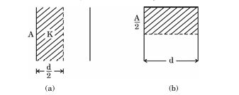
A parallel plate capacitor has plate area A and plate separation d. Half of the space between the plates is filled with a material of dielectric constant K in two ways as shown in the figure.
Find the values of the capacitance of the capacitors in the two cases.
In Young's double slit experiment, the separation between the two slits is 1·0 mm and the screen is 1·0 m away from the slits. A beam of light consisting of two wavelengths 500 nm and 600 nm is used to obtain interference fringes. Calculate :
(i) the distance between the first maxima for the two wavelengths.
(ii) the least distance from the central maximum, where the bright fringes due to both wavelengths coincide.
For λ = 500 nm (500 x 10^-9 m):
y1 = (1 * 500 x 10^-9 m * 1 m) / (1 x 10^-3 m) = 0.5 m = 50 cm.
For λ = 600 nm (600 x 10^-9 m):
y2 = (1 * 600 x 10^-9 m * 1 m) / (1 x 10^-3 m) = 0.6 m = 60 cm.
Therefore, the distance between the first maxima is |y2 - y1| = |60 cm - 50 cm| = 10 cm.
To find the least distance where the bright fringes coincide, we use the condition for coinciding maxima which is n1 * λ1 = n2 * λ2. Solving for the least common multiple gives us n1=6 for 500 nm and n2=5 for 600 nm. Their corresponding positions lead to y = 0.6 m for 600 nm and y = 0.5 m for 500 nm, indicating coinciding at L = 6 * (1/500)*1 m and L = 5 * (1/600)*1 m. The least distance is 30 cm.
An electron of mass m and charge -e is revolving anticlockwise around the nucleus of an atom.
(a) Obtain the expression for the magnetic dipole moment (μ) of the atom.
(b) If 𝐋⃗ is the angular momentum of electron, show that 𝐮⃗=-(e/2m) 𝐋⃗.
(b) The angular momentum L of the electron is L = m * v * r. Substituting v * r = L / m in the expression for μ, we get μ = (e / 2m) * L. Since the electron has negative charge, the direction of μ is opposite to L, so μ = -(e / 2m) * L. This shows that the magnetic dipole moment vector is opposite in direction to the angular momentum vector and proportional by the factor e / 2m.
A rectangular glass slab ABCD (refractive index 1·5) is surrounded by a transparent liquid (refractive index 1·25) as shown in the figure. A ray of light is incident on face AB at an angle i such that it is refracted out grazing the face AD. Find the value of angle i.
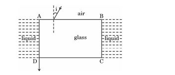
Explanation:
When light passes from the liquid to glass at face AB, it refracts inside the glass at angle r. The ray inside the glass then emerges from face AD at grazing incidence, meaning the refraction angle at AD is 90deg.
At the face AD, using Snell's law: n2 * sin r2 = n1 * sin 90deg => 1.5 * sin r2 = 1.25 * 1 => sin r2 = 1.25 / 1.5 = 0.8333. So, r2 = arcsin(0.8333) ≈ 56deg.
Since AB and AD are perpendicular faces of the rectangular slab, the sum of refracted angles inside the glass is 90deg (r + r2 = 90deg). Thus, r = 90deg - 56deg = 34deg.
At face AB, applying Snell's law: n1 * sin i = n2 * sin r => 1.25 * sin i = 1.5 * sin 34deg => sin i = (1.5 / 1.25) * sin 34deg = 1.2 * 0.5592 = 0.671.
Therefore, i = arcsin 0.671 ≈ 42deg.
Final answer: The angle of incidence i is approximately 42deg.
Two infinitely long straight wires '1' and '2' are placed d distance apart, parallel to each other, as shown in the figure. They are uniformly charged having charge densities λ and -λ/2 respectively. Locate the position of the point from wire '1' at which the net electric field is zero and identify the region in which it lies.
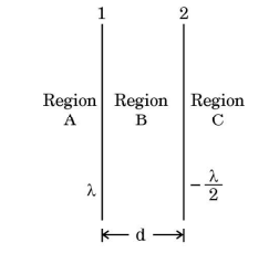
E1 = E2
λ / (2πε₀ x) = (λ/2) / (2πε₀ (d - x))
Simplifying,
1 / x = 1/(2(d - x))
Cross multiplying gives 2(d - x) = x,
2d - 2x = x
2d = 3x
x = 2d / 3
The point lies between the two wires since x < d and x > 0. Hence, the point where the net electric field is zero is located at a distance 2d/3 from wire '1' towards wire '2'.
Two small solid metal balls A and B of radii R and 2R having charge densities 2σ and 3σ respectively are kept far apart. Find the charge densities on A and B after they are connected by a conducting wire.
Radius of ball A = R, charge density on A = 2σ
Radius of ball B = 2R, charge density on B = 3σ
Step 1: Calculate initial charges on A and B.
Charge on A, q_A = charge density * surface area = 2σ * 4πR2 = 8πσR2
Charge on B, q_B = 3σ * 4π(2R)2 = 3σ * 4π * 4R2 = 48πσR2
Step 2: Total charge after connecting wire = q_A + q_B = 8πσR2 + 48πσR2 = 56πσR2
Step 3: When connected by a conducting wire, both spheres come to the same potential.
Potential on sphere A, V_A = k * q_A'/R
Potential on sphere B, V_B = k * q_B'/(2R)
Where q_A' and q_B' are the charges after connection and k is Coulomb's constant.
Equating potentials: q_A'/R = q_B'/(2R) -> 2q_A' = q_B'
Step 4: Total charge conservation: q_A' + q_B' = 56πσR2
Replace q_B' = 2q_A', so q_A' + 2q_A' = 3q_A' = 56πσR2
q_A' = (56/3)πσR2
q_B' = 2q_A' = (112/3)πσR2
Step 5: Find new charge densities:
Charge density = charge / surface area
σ_A' = q_A' / 4πR2 = (56/3)πσR2 / 4πR2 = 14σ/3
σ_B' = q_B' / 4π(2R)2 = (112/3)πσR2 / 16πR2 = 7σ/6
Final answer:
Charge density on A after connection = 14σ/3
Charge density on B after connection = 7σ/6
Section E
(i)Three batteries E₁, E₂ and E₃ of emfs and internal resistances (4 V, 2Ω ), (2 V, 4Ω ) and (6 V, 2Ω ) respectively are connected as shown in the figure. Find the values of the currents passing through batteries E₁, E₂ and E₃.
(ii) The ends of six wires, each of resistance R (= 10 ) are joined as shown in the figure. The points A and B of the arrangement are connected in a circuit. Find the value of the effective resistance offered by it to the circuit.
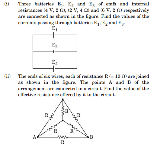
Let the currents be I₁, I₂ and I₃ through batteries E₁, E₂ and E₃ respectively.
Write Kirchhoff's loop equations considering the emf and internal resistances:
For loop 1: 4 - 2*I₁ - voltage across common resistors = 0
For loop 2: 2 - 4*I₂ - voltage across common resistors = 0
For loop 3: 6 - 2*I₃ - voltage across common resistors = 0
Using simultaneous equations solving (by substitution or matrix), we find I₁, I₂ and I₃.
(ii) Six wires each of resistance R = 10 Ω are connected as shown.
Analyzing the circuit, the wires form a combination of series and parallel connections.
First, identify which resistors are in series and which are in parallel.
Calculate the equivalent resistance stepwise:
- Combine series resistors by adding their resistances.
- Combine parallel resistors using 1/R_eq = 1/R₁ + 1/R₂ + ...
After simplification, the effective resistance between points A and B is found to be (5/6)*R = (5/6)*10 = 8.33 Ω.
Final answers:
(i) Currents I₁, I₂, and I₃ are found from solving Kirchhoff's equations.
(ii) Effective resistance between A and B is 8.33 Ω.
(i) Current I (= 1A) is passing through a copper rod (n = 8·5 *10²⁸ m⁻³) of varying cross-sections as shown in the figure. The areas of cross-section at points A and B along its length are 1·0 10⁻⁷ m² and 2·0 10⁻⁷ m² respectively. Calculate :
(I) the ratio of electric fields at points A and B.
(II) the drift velocity of free electrons at point B.
(ii) Two-point charges q₁ (= 16 μC) and q₂ (= 1 μC) are placed at points 𝑟⃗₁ = (3 m) 𝑖̂ and 𝑟⃗₂ = (4 m) 𝑗̂. Find the net electric field 𝐸⃗ at point 𝑟⃗₁ = (3 m) 𝑖̂+(4 m) 𝑗̂.
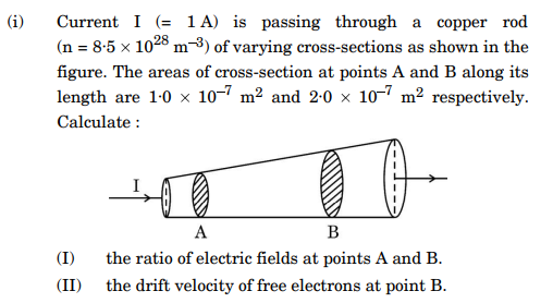
Current I = 1 A
Cross-sectional area at A, AA = 1.0 * 10-7 m2
Cross-sectional area at B, AB = 2.0 * 10-7 m2
Number density of free electrons, n = 8.5 * 1028 m-3
Current I is the same at both points since it is a series circuit.
Current density J at any point is J = I / A
Electric field E and current density J are related by J = sigma * E, where sigma is the conductivity of copper.
Since sigma is constant for the material, E is proportional to J.
Therefore, E = J / sigma => E proportional to J => E = I / (sigma * A)
Ratio of electric fields at points A and B:
EA / EB = (I / (sigma * AA)) / (I / (sigma * AB)) = AB / AA = (2.0 * 10-7) / (1.0 * 10-7) = 2
(II) Drift velocity vd is given by vd = I / (n * A * e), where e = 1.6 * 10-19 C (charge of one electron)
At point B:
vdB = I / (n * AB * e) = 1 / (8.5 * 1028 * 2.0 * 10-7 * 1.6 * 10-19)
Calculate denominator:
8.5 * 2.0 = 17, and 1028 * 10-7 * 10-19 = 10(28 -7 -19) = 102
So denominator = 17 * 1.6 * 102 = 27.2 * 102 = 2720
Therefore,
vdB = 1 / 2720 = 3.68 * 10-4 m/s
Final answers:
(I) Ratio of electric fields EA : EB = 2 : 1
(II) Drift velocity at B, vdB = 3.68 * 10-4 m/s
(i) Define self-inductance of a coil. Derive the expression for the energy required to build up a current I in a coil of self-inductance L.
(ii) The currents passing through two inductors of self-inductances 10 mH and 20 mH increase with time at the same rate.
Draw graphs showing the variation of :
(I) the magnitude of emf induced with the rate of change of current in each inductor.
(II) the energy stored in each inductor with the current flowing through it.
To find the energy stored, when current I flows through a coil of self-inductance L, first consider a small increase in current dI. The induced emf opposes the increase in current and work must be done to increase the current.
The power supplied at any instant is P = emf * current = L (dI/dt) * I
The incremental work done dW = power * dt = L I dI
Total energy stored, W = \int_{0}^{I} L I dI = L \int_{0}^{I} I dI = L [I2 / 2] = (1/2) L I2
Hence, energy stored in the magnetic field of the coil is W = (1/2) L I2.
(ii) Given two inductors with self-inductances 10 mH and 20 mH and currents increasing at the same rate dI/dt.
(I) The magnitude of emf induced . As dI/dt is same for both, emf is directly proportional to L.
Graph (emf vs dI/dt): Both graphs are straight lines starting from origin with slopes 10 mH and 20 mH respectively. The 20 mH inductor graph is steeper.
(II) Energy stored in each inductor W = (1/2) L I2.
Graph (energy stored vs current I): Both graphs are parabolas starting from origin, with the 20 mH inductor having a steeper curve because energy stored is proportional to L and I squared.
Thus, emf varies linearly with dI/dt with slope equal to L, and energy stored varies quadratically with current with coefficient (1/2) L.
(i) Define the term mutual inductance. Deduce the expression for the mutual inductance of two long coaxial solenoids of the same length having different radii and different number of turns.
(ii) The current through an inductor is uniformly increased from zero to 2 A in 40 s. An emf of 5 mV is induced during this period. Find the flux linked with the inductor at t = 10 s.
Derivation of Mutual Inductance M for two long coaxial solenoids:
Consider two long coaxial solenoids of the same length l. The inner solenoid S1 has radius r1 and number of turns per unit length n1. The outer solenoid S2 has radius r2 and number of turns per unit length n2.
The magnetic field inside the outer solenoid S2 due to current I2 is B = μ0 n2 I2.
Since the inner solenoid lies within the outer, the flux linked with the inner solenoid is due to this magnetic field.
Flux linked with one turn of inner solenoid = B × area of cross-section of inner solenoid = μ0 n2 I2 π r12.
Total flux linked with inner solenoid having N1 turns = N1 × (flux per turn) = n1 l × μ0 n2 I2 π r12.
Thus, .
From definition, , so mutual inductance M = μ0 π r12 n1 n2 l.
(ii) Calculation of flux linked at t = 10 s:
Given: Current I increases uniformly from 0 to 2 A in 40 s. emf ε = 5 mV = 5 × 10⁻³ V.
emf induced in an inductor, ε = L dI/dt where L is the inductance.
Since I changes uniformly, dI/dt = (2 - 0) / 40 = 1/20 A/s = 0.05 A/s.
So, L = ε / (dI/dt) = (5 × 10⁻³) / 0.05 = 0.1 H.
The flux linked with the inductor at any time t is Φ = L I.
At t = 10 s, current I = (2 / 40) × 10 = 0.5 A.
Therefore, flux Φ = 0.1 × 0.5 = 0.05 Wb.
Final answers:
(i) M = μ0 π r12 n1 n2 l
(ii) Flux linked at t = 10 s is 0.05 Weber.
(i) Draw a ray diagram of a reflecting telescope (Cassegrain) and explain the formation of image. State two important advantages that a reflecting telescope has over a refracting telescope.
(ii) In a refracting telescope, the focal length of the objective is 50 times the focal length of the eyepiece. When the final image is formed at infinity, the length of the tube is 102 cm. Find the focal lengths of the two lenses.
Image formation: The primary mirror forms a real, inverted and diminished image. The secondary convex mirror reflects this image through the hole in the primary mirror to the eyepiece lens which produces a virtual, enlarged and inverted final image visible to the observer.
Advantages of reflecting telescope over refracting telescope:
1. Reflecting telescopes do not suffer from chromatic aberration because mirrors reflect all colours equally.
2. They can be made much larger than lenses because mirrors can be supported from behind, avoiding sagging.
(a)(ii) Given: Focal length of objective fo = 50 * focal length of eyepiece fe,
Length of the telescope tube L = 102 cm.
For final image at infinity, length of tube L = fo + fe.
So, fo + fe = 102 cm.
Substitute fo = 50 fe,
50 fe + fe = 102 => 51 fe = 102 => fe = 102 / 51 = 2 cm.
Therefore, fo = 50 * 2 = 100 cm.
Answer: Focal length of objective = 100 cm, focal length of eyepiece = 2 cm.
(i) Write any two advantages of a compound microscope over a simple microscope. Draw a ray diagram for the image formation at the near point by a compound microscope and explain it.
(ii) A thin planoconcave lens with its curved face of radius of curvature R is made of glass of refractive index n₁. It is placed coaxially in contact with a thin equiconvex lens of same radius of curvature of refractive index n₂. Obtain the power of the combination lens.
1. A compound microscope has much greater magnifying power because it uses two lenses, the objective and the eyepiece.
2. It can produce a real, inverted, and magnified image of the object which can then be further magnified by the eyepiece for clearer observation.
Ray Diagram and Explanation:
The compound microscope consists of two convex lenses placed coaxially: the objective lens near the object and the eyepiece near the eye. The objective forms a real, inverted, and magnified image of the object, which lies between its focal length and twice the focal length. This image acts as an object for the eyepiece which forms a virtual, enlarged image at the near point of the eye (typically 25 cm). The final image is highly magnified, inverted, and virtual, suitable for detailed observation.
(ii) Power of Combination Lens:
Given: A planoconcave lens with radius of curvature R, refractive index n₁, and an equiconvex lens with the same radius R, refractive index n₂, placed in contact coaxially.
Step 1: For the planoconcave lens, focal length f₁ is given by lens maker's formula:
1/f₁ = (n₁ - 1)(-1/R), because it is concave and only one curved surface contributes (the plane surface radius is infinite).
Simplifying: f₁ = -R/(n₁ - 1)
Step 2: For the equiconvex lens, focal length f₂ is:
1/f₂ = (n₂ - 1)(1/R + 1/R) = 2(n₂ - 1)/R
So, f₂ = R/[2(n₂ - 1)]
Step 3: Power of lenses:
P₁ = 100/f₁ = 100 * (n₁ - 1)/(-R) = -100(n₁ - 1)/R
P₂ = 100/f₂ = 100 * 2(n₂ - 1)/R = 200(n₂ - 1)/R
Step 4: Since lenses are in contact, total power P = P₁ + P₂ = [-100(n₁ - 1) + 200(n₂ - 1)]/R
Hence, the power of the combination lens is P = [200(n₂ - 1) - 100(n₁ - 1)]/R.
Paper Details
CBSE Board Exam 2025
Class
Class 12 PCM
Subject
Physics
Year
2025
Set
Set 5
Other Years — Physics