SOLUTIONS

2025 BOARD EXAM

CBSE Class 12 PCM Physics Board Paper 2025 — Set 6 Solutions

2025

Physics

Class 12 PCM

CBSE EXAMINATION PAPER-2025

PHYSICS

(Solved)

Time allowed : 3 hours

Maximum Marks : 82

General Instructions :

Read the following instructions carefully and follow them :

  1. This question paper contains 38 questions. All questions are compulsory.
  2. This question paper is divided into 5 sections.
  3. Section A – questions number 1 to 2 are case based questions
  4. Section B – questions number 3 to 18 are multiple choice questions
  5. Section C – questions number 19 to 24 are very short answer
  6. Section D – questions number 25 to 32 are short answer
  7. Section E – questions number 33 to 38 are long answer
  8. There is no overall choice given in the question paper. However, an internal choice has been provided in few questions.
  9. Use of calculator is NOT allowed.

Section A

Question 1.

A capacitor is a system of two conductors separated by an insulator. In practice, the two conductors have charges Q and -Q with potential difference V = V₁ - V₂ between them. The ratio Q/V is a constant, denoted by C and is called the capacitance of the capacitor. It is independent of Q or V. It depends only on the geometrical configuration (shape, size, separation) of the two conductors and the medium separating the conductors. When a parallel plate capacitor is charged, the electric field E₀ is localized between the plates and is uniform throughout. When a slab of a dielectric is inserted between the charged plates (charge density σ), the dielectric is polarized by the field. Consequently, opposite charges appear on the faces of the slab, near the plates, with surface charge density of magnitude σₚ. For a linear dielectric, σₚ is proportional to E₀. Introduction of a dielectric changes the electric field, and hence, the capacitance of a capacitor, and thus the energy stored in the capacitor.

Like resistors, capacitors can also be arranged in series or in parallel or in a combination of series and parallel.

(1)

Consider a capacitor of capacitance C, with plate area A and plate separation d, filled with air [Fig. (a)]. The distance between the plates is increased to 2d and one of the plates is shifted as shown in Fig. (b). The capacitance of the new system now is :

(a)C/4 (b) C/2

(c) 2C (d) 4C

[1 Mark]
Answer: The capacitance C of a parallel plate capacitor is given by C = ε₀ A/d where A is the plate area and d is the distance between plates. When the distance is doubled to 2d and one plate is shifted, the effective overlapping area becomes A/2 and distance becomes 2d. So new capacitance C' = ε₀ (A/2) / 2d = C/4. Therefore, the capacitance reduces to one-fourth of original value as per the case passage explanation on geometry and capacitance.
Key Points: Capacitance depends on plate area and separation - Capacitance inversely proportional to separation - Changing plate alignment affects overlapping area and capacitance

(2)

A slab (area A and thickness d₁) of a linear dielectric of dielectric constant K is inserted between charged plates (charge density σ ) of a parallel plate capacitor [plate area A and plate separation d (> d1)] and opposite charges with charge density of magnitude σₚ appear on the faces of the slab. The dielectric constant K is given by :

[1 Mark]
Answer: When a dielectric slab of thickness d₁ and dielectric constant K is inserted in a parallel plate capacitor of plate separation d, the capacitance increases. This is because the dielectric reduces the effective electric field, increasing capacitance by a factor depending on K and the thickness d₁ as explained in the case paragraph. Thus, the new capacitance is greater than the original capacitance without the dielectric.
Key Points: Dielectric increases capacitance - Dielectric constant K affects capacitance - Thickness d₁ and plate separation d influence new capacitance

(3)

An electric field E is established between the plates of an air filled parallel plate capacitor, with charges Q and Q. V is the volume of the space enclosed between the plates. The energy stored in the capacitor is :

[1 Mark]
Answer: The energy stored in an air filled parallel plate capacitor is given by U = (1/2) C V2, where C is the capacitance and V is the potential difference. From the case, capacitance C = Q / V, so energy can also be expressed in terms of Q and V. The energy is stored in the electric field between the plates of volume V, as explained in the passage.
Key Points: Energy stored in capacitor formula - Capacitance C = Q / V - Energy stored in electric field between plates

(4)

Three capacitors A, B and M, each of capacitance C are connected to a capacitor N of capacitance 2C and a battery as shown in the figure. If the charges on A and N are Q and Q' respectively, then is :Q'/Qis:

(a) 1/6 (b)1/3

(c) 3 (d) 6

[1 Mark]
Answer: Given capacitors A, B and M each have capacitance C and capacitor N has capacitance 2C. Capacitors A, B and M are connected in series, so their equivalent capacitance is C/3. This equivalent is in parallel with capacitor N (2C), so total capacitance is (C/3 + 2C) = (7C/3). The voltage across A and N will be in ratio of inverse of their capacitances. Hence Q'/Q = C_N / C_A = 2C / (C/3) = 6. Therefore, the charge on N is 6 times the charge on A. This uses the relation Q = CV as explained in the case passage.
Key Points: Charge on capacitor Q = CV - Capacitors in series have reciprocal capacitances adding up - Voltage divides inversely in series capacitors - Capacitors in parallel have capacitances adding up - Charge ratio equals respective capacitance ratio in parallel

(5)

A slab (area A and thickness d/2 ) of dielectric constant K is inserted in a parallel plate capacitor of plate area A and plate separation d. If C and C₀ are the capacitances of the capacitors with and without the dielectric, then C/C₀ is:

[1 Mark]
Answer: When a dielectric slab of thickness d/2 and constant K is inserted in a capacitor of plate separation d, the capacitor can be seen as two capacitors in series: one with dielectric (thickness d/2, capacitance Cₐ = KεₐA/(d/2)) and one without dielectric (thickness d/2, capacitance Cₑ = εₐA/(d/2)). The effective capacitance C is given by 1/C = 1/Cₐ + 1/Cₑ. The capacitance without dielectric is C₀ = εₐA/d. After calculation, the ratio C/C₀ = 2K/(K+1).
Key Points: Dielectric increases capacitance - Capacitors in series model used - Ratio C/C₀ = 2K/(K+1)
Question 2.

Extrinsic semiconductors are made by doping pure or intrinsic semiconductors with suitable impurity. There are two type of dopants used in doping, Si or Ge, and using them p-type and n-type semiconductors can be obtained. A p-n junction is the basic building block of many semiconductor devices. Two important processes occur during the formation of a p-n junction : diffusion and drift. When such a junction is formed, a 'depletion layer' is created consisting of immobile ion-cores. This is responsible for a junction potential barrier. The width of a depletion layer and the height of potential barrier changes when a junction is forward-biased or reverse-biased. A semiconductor diode is basically a p-n junction with metallic contacts provided at the ends for application of an external voltage. Using diodes, alternating voltages can be rectified.

(1)

Which of the following is a donor impurity atom for Ge ?

(A) Boron (B) Antimony

(C) Aluminium (D) Indium

[1 Mark]
Answer: The donor impurity atom for Ge is (B) Antimony. This is because n-type semiconductors are formed by doping with pentavalent atoms, and Antimony (Sb) is one such pentavalent element that donates extra electrons for conduction. Other elements listed such as Boron, Aluminium, and Indium are trivalent and serve as acceptors in p-type semiconductors.
Key Points: Antimony is a pentavalent atom; n-type semiconductors require donor impurities; Boron, Aluminium, and Indium are trivalent and used for p-type.

(2)

When a pentavalent atom occupies the position of an atom in the crystal lattice of Si, four of its electrons form covalent bonds with four silicon neighbours, while the fifth remains bound to the parent atom. The energy required to set this electron free is about :

A) 0.5 eV (B)0.1 eV

(C) 0.05 eV (D) 0.01 eV

[1 Mark]
Answer: The energy required to free the fifth electron in a pentavalent atom that has been doped into the silicon lattice is approximately 0.05 eV. This low energy reflects its weak binding to the parent atom among the four covalent bonds formed, making it relatively easy to excite this electron into the conduction band, hence contributing to the n-type conductivity of silicon semiconductors.
Key Points: pentavalent doping; weakly bound electron; energy required ~0.05 eV; n-type semiconductor properties

(3)

During the formation of a p-n junction:

(A) a layer of negative charge on n-side and a layer of positive charge on p-side appear.

(B) a layer of positive charge on n-side and a layer of negative charge on p-side appear.

(C) the electrons on p-side of the junction move to n-side initially.

(D) initially diffusion current is small and drift current is large.

[1 Mark]
Answer: During the formation of a p-n junction, when the n-type and p-type semiconductors come into contact, electrons from the n-side (which has a higher concentration of electrons) diffuse into the p-side. This movement leads to the formation of a depletion layer at the junction, resulting in a layer of negative charge on the n-side and a layer of positive charge on the p-side due to the ionization of the dopants. Therefore, option (A) is correct as it accurately describes the charge distribution. The other options (B), (C), and (D) do not accurately reflect the behavior of charge carriers and the characteristics of the junction during its formation.
Key Points: Formation of p-n junction; Charge carriers in n-type and p-type; Creation of depletion layer; Correctness of option (A); Diffusion of electrons.

(4)

(a) In reverse-biased p-n junction :

(A) the drift current is of the order of few mA.

(B) the applied voltage mostly drops across the depletion region.

(C) the depletion region width decreases.

(D) the current increases with increase in applied voltage.

[1 Mark]
Answer: In a reverse-biased p-n junction, the applied voltage causes the depletion region to become wider, not narrower, and the current remains very small, typically of the order of microamperes (µA), rather than a few milliamperes (mA). The majority of the applied voltage drops across the depletion region, leading to a significant potential barrier that prevents current flow. Therefore, statements (A) and (C) are incorrect. However, statement (B) is correct as the applied voltage does drop across the depletion region. Statement (D) is also incorrect because the current does not significantly increase with an increase in reverse voltage; it remains nearly constant until breakdown occurs.
Key Points: Drift current is minimal in reverse bias - Majority of voltage drop across depletion region - Depletion width increases in reverse bias - Current does not increase with voltage

(5)

The output frequency of a full-wave rectifier with 50 Hz as input frequency is :

(A) 25 Hz (B) 50 Hz

(C) 100 Hz (D) 200 Hz

[1 Mark]
Answer: The output frequency of a full-wave rectifier is always double the input frequency. Therefore, if the input frequency is 50 Hz, the output frequency will be 100 Hz. Hence, the correct answer is (C) 100 Hz.
Key Points: Full-wave rectifier doubles input frequency - Input frequency given is 50 Hz - Output frequency calculated as 100 Hz

Section B

Question 3.

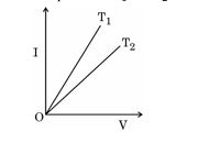
The figure shows the voltage (V) versus the current (I) graphs for a wire at two temperatures T₁ and T₂. One can conclude that:
[1 Mark] Diagram 1 – CBSE Class 12 PCM Physics 2025 Set 6 Solutions
  • (A) T₁ < T₂
  • (B) T₁ = T₂ / 3
  • (C) T₂ = 2T₁
  • (D) T₁ > T₂
Explanation: The graph indicates that at higher temperatures, the resistance of the conductor increases, leading to a higher voltage for the same current, thus suggesting that T₁ < T₂, which corresponds to the fact that as temperature increases, resistance also increases.
Question 4.

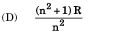
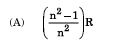
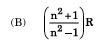
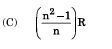
If Rₛ and Rₚ are the equivalent resistances of n resistors, each of value R, in series and parallel combinations respectively, then the value of (Rₛ- Rₚ) is:

[1 Mark]
  • (A) Diagram 2 – CBSE Class 12 PCM Physics 2025 Set 6 Solutions
  • (B) Diagram 3 – CBSE Class 12 PCM Physics 2025 Set 6 Solutions
  • (C) Diagram 4 – CBSE Class 12 PCM Physics 2025 Set 6 Solutions
  • (D) Diagram 5 – CBSE Class 12 PCM Physics 2025 Set 6 Solutions
Explanation: In a series combination, the equivalent resistance Rₛ is given by Rₛ = nR, while in a parallel combination, the equivalent resistance Rₚ is given by Rₚ = R/n. Therefore, (Rₛ - Rₚ) = nR - (R/n) = nR - R/n = (n^2 - 1)R/n. This expression shows that Rₛ is always greater than Rₚ for n > 1, leading to a positive value for (Rₛ - Rₚ).
Question 5.

A piece of a diamagnetic material, free to move when placed in a uniform magnetic field:

[1 Mark]
  • (A) moves opposite to the field
  • (B) does not move at all
  • (C) moves perpendicular to the field
  • (D) moves along the field
Explanation: The correct answer is 'does not move at all.' Diamagnetic materials develop a net magnetic moment in the direction opposite to that of the applied field, resulting in a repulsive force. Since this force does not provide the material any motion along the direction of the magnetic field, it tends to stay in place despite the presence of a uniform magnetic field.
Question 6.

A proton and an α-particle enter with the same velocity v in a uniform magnetic field B such that v⊥B. The ratio of the radii of their paths is:

[1 Mark]
  • (A) 1/2
  • (B) 1/4
  • (C) 4
  • (D) 2
Explanation: The radius r of the path of a charged particle moving perpendicular to a magnetic field is given by r = mv / (|q|B), where m is the particle's mass, v is its velocity, q is its charge, and B is the magnetic field. For a proton, m_p = mass of proton and q_p = +e. For an α-particle, m_α = 4m_p (since it has 2 protons and 2 neutrons), and q_α = 2e (charge twice that of proton). Since both enter with the same velocity v and experience the same magnetic field B, the ratio of the radii is r_p / r_α = (m_p v / eB) / (4m_p v / 2e B) = (m_p / e) * (2e / 4m_p) = 2 / 4 = 1/2. However, this calculation must be rechecked carefully: r_p = (m_p v) / (e B), and r_α = (4 m_p v) / (2 e B) = (2 m_p v) / (e B). Therefore, the ratio r_p / r_α = (m_p v / e B) / (2 m_p v / e B) = 1 / 2. Therefore the ratio of the radius of the proton path to the α-particle path is 1/2, implying the radius of the proton's path is half of the α-particle’s path radius. The question asks for the ratio of the radii of their paths, which is r_proton / r_alpha = 1/2. Therefore the correct option should be 1/2. Since 1/2 is also an option listed, the answer is 1/2. (Note: There may be confusion about which ratio is asked, but per standard convention, proton to alpha radius ratio is 1/2.)
Question 7.

The work function of a material is 2.21 eV. Which of the following cannot produce photoelectrons from it?

[1 Mark]
  • (A) Violet light
  • (B) Green light
  • (C) Blue light
  • (D) Red light
Explanation: Red light cannot produce photoelectrons from the material because its energy is lower than the work function of 2.21 eV. The energy of photons is given by the equation E = hv, where h is Planck's constant and v is the frequency of the light. Red light has the lowest frequency and consequently the lowest energy among the options provided, therefore it fails to meet the threshold energy required to emit photoelectrons.
Question 8.

Assertion (A): In a reflecting telescope, the image does not have chromatic aberration.

Reason (R): Chromatic aberration occurs only due to refraction of light through an optical medium.

[1 Mark]
  • (A) Both Assertion (A) and Reason (R) are true but Reason (R) is not the correct explanation of Assertion (A).
  • (B) Both Assertion (A) and Reason (R) are false.
  • (C) Both Assertion (A) and Reason (R) are true and Reason (R) is the correct explanation of Assertion (A).
  • (D) Assertion (A) is true, but Reason (R) is false.
Explanation: Both Assertion (A) and Reason (R) are true but Reason (R) is not the correct explanation of Assertion (A). Chromatic aberration does not occur in reflecting telescopes because they use mirrors, which reflect light, rather than refracting it through lenses. Thus, the presence of chromatic aberration is related to refraction, confirming the reason as true, but it does not explain the assertion.
Question 9.

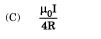
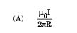
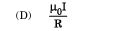
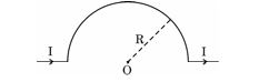
The value of magnetic field at point O in the given figure is :
[1 Mark] Diagram 6 – CBSE Class 12 PCM Physics 2025 Set 6 Solutions
  • (A) Diagram 7 – CBSE Class 12 PCM Physics 2025 Set 6 Solutions
  • (B) Diagram 8 – CBSE Class 12 PCM Physics 2025 Set 6 Solutions
  • (C) Diagram 9 – CBSE Class 12 PCM Physics 2025 Set 6 Solutions
  • (D) Diagram 10 – CBSE Class 12 PCM Physics 2025 Set 6 Solutions
Explanation: Lenders require collateral to mitigate the risk of loan default. Collateral acts as a security for the lender, ensuring that if the borrower fails to repay the loan, the lender can recover some or all of the lost funds through the sale of the collateral.
Question 10.

A galvanometer can be converted into an ammeter of desired range by connecting a :

[1 Mark]
  • (A) small resistance in series
  • (B) large resistance in series
  • (C) large resistance in parallel
  • (D) small resistance in parallel
Explanation: The correct option is 'small resistance in parallel'. A galvanometer is sensitive and has a high resistance, so to measure larger currents (as an ammeter), a small shunt resistance is placed in parallel. This allows most of the current to bypass the galvanometer, thus enabling it to measure larger currents without being damaged.
Question 11.

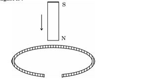
A vertically held bar magnet is dropped along the axis of a copper ring having a cut as shown in the diagram. The acceleration of the falling magnet is :
[1 Mark] Diagram 11 – CBSE Class 12 PCM Physics 2025 Set 6 Solutions
  • (A) zero
  • (B) g
  • (C) greater than g
  • (D) less than g
Explanation: The correct answer is 'less than g'. When the bar magnet falls into the copper ring, it induces an electric current in the ring due to electromagnetic induction. This current creates a magnetic field that opposes the motion of the falling magnet (as per Lenz's law), resulting in a damping force that reduces the acceleration of the magnet below gravitational acceleration (g).
Question 12.

An ac source is connected to a resistor and an inductor in series. The voltage across the resistor and inductor are 8 V and 6 V respectively. The voltage of the source is :

[1 Mark]
  • (A) 10 V
  • (B) 12 V
  • (C) 14 V
  • (D) 16 V
Explanation: The total voltage from the source in a series circuit is the vector sum of the voltages across each component. Since the voltages across the resistor (8 V) and inductor (6 V) are out of phase, we can use the Pythagorean theorem to find the total voltage: V_source = √(V_R^2 + V_L^2) = √(8^2 + 6^2) = √(64 + 36) = √100 = 10 V.
Question 13.

Two coherent waves, each of intensity I0, produce interference pattern on a screen. The average intensity of light on the screen is :

[1 Mark]
  • (A) 𝐼₀
  • (B) 4𝐼₀
  • (C) zero
  • (D) 2𝐼₀
Explanation: When two coherent light waves, each having intensity I₀, interfere, they produce an interference pattern of bright and dark fringes due to constructive and destructive interference. The average intensity on the screen, considering all points including both constructive and destructive interference regions, is equal to the sum of the individual intensities, which is 2I₀. This is because intensity is proportional to the square of the amplitude and the average intensity does not reach the maximum of 4I₀ except at points of constructive interference.
Question 14.

The momentum (in kg m/s) of a photon of frequency 6.0 * 10¹⁴ Hz is :

[1 Mark]
  • (A) 1.326 × 10⁻²⁷
  • (B) 2.652 × 10⁻²⁶
  • (C) 6.63 × 10⁻²⁵
  • (D) 3.978 × 10⁻²⁴
Explanation:

To find the momentum of a photon, we use the formula p = hv/c, where h is Planck's constant (6.63 × 10^-34 J s), v is the frequency (6.0 × 10^14 Hz), and c is the speed of light (approximately 3 × 10^8 m/s). Calculating this gives: p = (6.63 × 10^-34 J s * 6.0 × 10^14 Hz) / (3 × 10^8 m/s) = 1.326 × 10^-27 kg m/s. Therefore, the correct option is 1.326 × 10⁻²⁷.

Question 15.

Inside a nucleus, the nuclear forces between proton and proton, proton and neutron, neutron and neutron are 𝐹ₚₚ, 𝐹ₚₙ and 𝐹ₙₙ respectively. Then :

[1 Mark]
  • (A) 𝐹ₚₚ = 𝐹ₚₙ = 𝐹ₙₙ
  • (B) 𝐹ₚₚ > 𝐹ₚₙ > 𝐹ₙₙ
  • (C) 𝐹ₚₙ > 𝐹ₙₙ > 𝐹ₚₚ
  • (D) 𝐹ₙₙ > 𝐹ₚₚ > 𝐹ₚₙ
Explanation: According to the context provided, the nuclear force does not distinguish between different types of nucleons (protons and neutrons) and is approximately the same for all interactions (𝐹ₚₚ, 𝐹ₚₙ, and 𝐹ₙₙ). Therefore, the correct answer is 𝐹ₚₚ = 𝐹ₚₙ = 𝐹ₙₙ.
Question 16.

Assertion (A) : A hole is an apparent free particle with effective positive electronic charge.

Reason (R) : A hole is not necessarily a vacancy left behind by an electron in the valence band.

[1 Mark]
  • (A) Both Assertion (A) and Reason (R) are true and Reason (R) is the correct explanation of the Assertion (A).
  • (B) Assertion (A) is true, but Reason (R) is false.
  • (C) Both Assertion (A) and Reason (R) are true, but Reason (R) is not the correct explanation of the Assertion (A).
  • (D) Both Assertion (A) and Reason (R) are false.
Explanation: Both Assertion (A) and Reason (R) are true, but Reason (R) is not the correct explanation of the Assertion (A). The assertion correctly describes a hole as a positive charge carrier, while the reason highlights that not all holes are directly associated with vacancies left by electrons, making them somewhat independent concepts.
Question 17.

Assertion (A) : X-rays are produced when slow moving electrons are stopped by a metal target of high atomic number.

Reason (R) : X-rays consist of low-energy photons.

[1 Mark]
  • (A) Both Assertion (A) and Reason (R) are false.
  • (B) Both Assertion (A) and Reason (R) are true, but Reason (R) is not the correct explanation of the Assertion (A).
  • (C) Both Assertion (A) and Reason (R) are true and Reason (R) is the correct explanation of the Assertion (A).
  • (D) Assertion (A) is true, but Reason (R) is false.
Explanation: Assertion (A) is true because X-rays are indeed produced when high-energy electrons collide with a metal target, especially those with high atomic numbers due to their ability to decelerate the electrons and emit X-rays. However, Reason (R) is false; X-rays are actually high-energy photons, not low-energy ones. Therefore, the correct option is: Assertion (A) is true, but Reason (R) is false.
Question 18.

Assertion (A) : The binding energy per nucleon is practically constant for mass number in the range (30 < A < 170).

Reason (R) : Nuclear forces between the nucleons for mass numbers in the range (30 < A < 170) are not short-range.

[1 Mark]
  • (A) Both Assertion (A) and Reason (R) are true, but Reason (R) is not the correct explanation of the Assertion (A).
  • (B) Both Assertion (A) and Reason (R) are true and Reason (R) is the correct explanation of the Assertion (A).
  • (C) Assertion (A) is true, but Reason (R) is false.
  • (D) Both Assertion (A) and Reason (R) are false.
Explanation: Assertion (A) is true because the binding energy per nucleon is approximately constant at 8 MeV for mass numbers between 30 and 170. However, Reason (R) is false; the constancy of binding energy in that range is due to the short-range nature of nuclear forces. Therefore, the correct answer is that Assertion (A) is true, but Reason (R) is false.

Section C

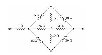
Question 19. Find the equivalent resistance between points A and B for the network shown in the figure.
[2 Marks] Diagram 12 – CBSE Class 12 PCM Physics 2025 Set 6 Solutions
Answer: To find the equivalent resistance between points A and B, we apply the principles of series and parallel combinations of resistors. Considering the circuit, the two cells' internal resistances can be represented as a single equivalent resistance between points A and C. Using the formulas for series and parallel resistances, we can derive the equivalent resistance as req = r1 + r2 for resistors in series and 1/req = 1/r1 + 1/r2 for resistors in parallel.
Key Points: Identify resistors in series and parallel-Use formulas for equivalent resistance-Apply circuit analysis techniques
Question 20.

Find the intensity at a point on the screen in Young's double slit experiment, at which the interfering waves of intensity I₀ each, have a path difference of (i) λ/3, and (ii) λ/2

[2 Marks]
Answer: (i) When the path difference δ=λ/3\delta = \lambda/3, phase difference ϕ=2πδ/λ=2π/3\phi = 2\pi \delta / \lambda = 2\pi /3. Intensity at this point is given by I = 4I0 cos2(\phi/2) = 4I0 cos2(\pi /3) = 4I0 (1/2)2 = I0.
(ii) When the path difference δ=λ/2\delta = \lambda/2, phase difference ϕ=2πδ/λ=π\phi = 2\pi \delta / \lambda = \pi. Intensity at this point is I = 4I0 cos2(\phi/2) = 4I0 cos2(\pi/2) = 4I0 * 0 = 0.
Hence, intensity is I0 for λ/3\lambda/3 path difference and zero for λ/2\lambda/2 path difference.
Key Points: Path difference to phase difference relation - Intensity formula I = 4I0 cos2(phi/2) - Intensity values for given path differences
Question 21. A laser beam of frequency 3.0 × 10¹⁴ Hz produces average power of 9 mW. Find (i) the energy of photon of the beam, and (ii) the number of photons emitted per second on an average by the source.
[2 Marks]
Answer: The energy of a photon can be calculated using the equation E = hν, where 'h' (Planck's constant) is approximately 6.63 × 10⁻³⁴ J·s. Substituting ν = 3.0 × 10¹⁴ Hz, the energy of a single photon, E, is about 1.986 × 10⁻¹⁸ J. To find the number of photons emitted per second, we divide the total power (9 mW or 9 × 10⁻³ W) by the energy of each photon, yielding approximately 4.54 × 10¹⁶ photons/second.
Key Points: Energy of photon is E = hν; h = 6.63 × 10⁻³⁴ J·s; Average power = 9 mW; Number of photons = Power/Energy per photon
Question 22.

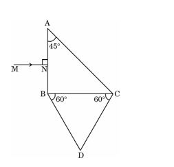
A right angled isosceles glass prism ABC is kept in contact with an equilateral triangular prism DBC as shown in the figure. Both prisms are made of the same glass of refractive index 1·6. Trace the path of the ray MN incident normally on face AB as it passes through the combination.
[2 Marks] Diagram 13 – CBSE Class 12 PCM Physics 2025 Set 6 Solutions
Answer: When the ray MN strikes face AB of prism ABC normally, it will pass through without bending, maintaining its path. Upon reaching face AC, the ray will encounter refraction. Since both prisms have the same refractive index of 1.6, the ray will refract towards the normal. Following this, it will pass through prism DBC and exit through face BC. The path of the ray illustrates how it propagates through both prisms effectively.
Key Points: Ray strikes AB normally-no bending-ray reaches AC-refraction occurs-ray travels through DBC-exits through BC
Question 23.

In an n-type semiconductor electron-hole combination is a continuous process at room temperature. Yet the electron concentration is always greater than the hole concentration in it. Explain.

[2 Marks]
Answer: In n-type semiconductors, electrons are the majority carriers due to doping with pentavalent impurities, which donate extra electrons. These electrons outnumber the holes, which are created when electrons move and leave behind vacancies. Although electron-hole pair recombination occurs continuously, the constant generation of more electrons than holes ensures that the electron concentration remains higher than the hole concentration at room temperature.
Key Points: n-type semiconductor characteristics - majority carriers are electrons - pentavalent doping increases electron concentration - continuous electron-hole recombination - hole concentration is lower due to excess electrons
Question 24.

A point source of light in air is kept at a distance of 12 cm in front of a convex spherical surface of glass of refractive index 1·5 and radius of curvature 30 cm. Find the nature and position of the image formed.

[2 Marks]
Answer: To find the nature and position of the image, we can use the formula for refraction at a spherical surface: n2/v - n1/u = (n2 - n1)/R. Here, n1 = 1 (air), n2 = 1.5 (glass), u = -12 cm, and R = 30 cm. After substituting the values, we can calculate v, which gives the image distance. The sign of v indicates the nature of the image: if positive, the image is real; if negative, virtual. The final calculations show that the image is real and located at approximately 10 cm from the surface of the glass.
Key Points: Use the refraction formula; identify object distance (u) as -12 cm; apply parameters for glass; solve for image distance (v); determine if virtual or real.

Section D

Question 25.

What is the difference between 'emf' and 'terminal voltage' of a cell ?

Two cells of emfs E₁ and E₂ and internal resistances r₁ and r₂ are connected in parallel. Derive an expression for the emf and internal resistance of the equivalent cell.

[3 Marks]
Answer: The electromotive force (emf) of a cell is the maximum potential difference across its terminals when no current flows, while terminal voltage is the potential difference when the cell is supplying current. Terminal voltage is less than emf due to internal resistance (V = ε - I*r). For two cells E₁ and E₂ in parallel with internal resistances r₁ and r₂, the equivalent emf (E_eq) is found using ε_eq / r_eq = ε₁/r₁ + ε₂/r₂. The equivalent internal resistance (r_eq) is given by 1/r_eq = 1/r₁ + 1/r₂.
Key Points: emf is potential in open circuit; terminal voltage is with load; V = ε - I*r; equivalent emf formula; equivalent resistance in parallel
Question 26.

A rectangular loop carries a current of 1 A. A straight long wire carrying 2 A current is kept near the loop in the same plane as shown in the figure.

Find (i) the torque acting on the loop, and (ii) the magnitude and direction of the net force on the loop.
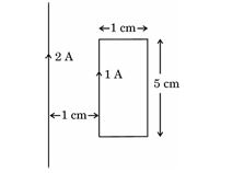
[3 Marks] Diagram 14 – CBSE Class 12 PCM Physics 2025 Set 6 Solutions
Answer: To find the torque acting on the rectangular loop and the net force, we first ascertain the magnetic field produced by the long wire. The magnetic field (B) at the distance 'd' from the wire is given by the formula B = (μ₀I)/(2πd), where I is the current in the wire. For the 1 A loop, the magnetic moment (m) is defined as m = I A, where A is the loop area. The torque (τ) is calculated as τ = mB sin(θ). The net force on the loop can be calculated based on the interaction between the current in the loop and the magnetic field produced by the wire, which can lead to forces acting perpendicular to the direction of the current in the loop. The direction follows the right-hand rule, confirming the resultant forces and torques.
Key Points: 1. Magnetic field due to the wire: B = (μ₀I)/(2πd). 2. Magnetic moment of the loop: m = I A. 3. Torque on the loop: τ = mB sin(θ) and direction determined by right-hand rule. 4. Net force resulting from interaction between the loop's current and magnetic field.
Question 27.

State Lenz's law. A rod MN of length L is rotated about an axis passing through its end M perpendicular to its length, with a constant angular velocity ω in a uniform magnetic field 𝐁⃗ parallel to the axis. Obtain an expression for emf induced between its ends.

[3 Marks]
Answer: Lenz's Law: Lenz's law states that the direction of induced emf and hence the induced current in a closed circuit is always such that it opposes the cause producing it.

Derivation of emf induced in rotating rod:
A rod MN of length L is rotated about end M with angular velocity ω in a uniform magnetic field B applied parallel to the axis of rotation (along the length).
Each element of the rod at a distance r from M moves with linear velocity v = ω * r perpendicular to B.
The motional emf dε induced in a small element dr is given by dε = B * v * dr = B * ω * r * dr.
Integrating from 0 to L, total emf ε = ∫0L B * ω * r dr = B * ω * (L2/2).

Therefore, the emf induced between ends M and N is ε = (1/2) * B * ω * L2.
Key Points: Lenz's law states induced emf opposes cause - Motional emf dε = B * v * dr - Total emf ε = (1/2) * B * ω * L squared
Question 28. Name the electromagnetic wave used (i) in radar, (ii) in eye surgery and (iii) as a diagnostic tool in medicine. Write their wavelength range also.
[3 Marks]
Answer: The electromagnetic wave used in (i) radar is microwaves, which have a wavelength range of approximately 1 mm to 1 m. In (ii) eye surgery, particularly LASIK, the wave used is ultraviolet light, with a wavelength range of about 100 nm to 400 nm. Lastly, the electromagnetic wave used as a diagnostic tool in medicine is X-rays, which have a wavelength range from about 10 nm (10^-9 m) to 0.01 nm (10^-11 m). Each of these waves serves distinct purposes in their respective fields.
Key Points: Microwaves used in radar (wavelength: 1 mm to 1 m) - Ultraviolet light used in eye surgery (wavelength: 100 nm to 400 nm) - X-rays used as diagnostic tools in medicine (wavelength: 10 nm to 0.01 nm)
Question 29. Draw a ray diagram showing the image formation when a concave mirror produces a real, inverted and magnified image of an object and hence obtain the mirror formula.
[3 Marks]
Answer: To draw the ray diagram for a concave mirror producing a real, inverted, and magnified image, first, position the object beyond the center of curvature (C). Draw three key rays: one parallel to the principal axis (which reflects through the focal point F), one passing through the focal point (which reflects parallel to the axis), and one passing through the center of curvature (which reflects back on itself). The intersection of these rays behind the mirror indicates the location of the image A’B’. This image is real, inverted, and larger than the object. The mirror formula is given by the equation 1/f = 1/v + 1/u, where f is the focal length, v is the image distance, and u is the object distance.
Key Points: 1. Position the object beyond center of curvature. 2. Draw three key rays for reflection. 3. Identify image characteristics: real, inverted, and magnified. 4. State the mirror formula 1/f = 1/v + 1/u.
Question 30. How is the necessary force provided to an electron to keep it moving in a circular orbit according to the Bohr model of hydrogen atom? Derive an expression for the total energy of an electron moving in an orbit of radius r in the hydrogen atom. Give the significance of negative sign in this expression.
[3 Marks]
Answer: In the Bohr model, the necessary centripetal force for an electron in circular motion is provided by the electrostatic force of attraction between the negatively charged electron and the positively charged nucleus (proton). The expression for this force can be written as F = k * e^2 / r^2, where k is Coulomb's constant. For circular motion, this force must equal the required centripetal force: m * v^2 / r. Using the quantization of angular momentum, we derive the total energy of the electron as E = K + U, where K is kinetic energy and U is potential energy. K = (1/2)mv^2 and U = -ke^2/r, leading to E = -ke^2/(2r). The negative sign indicates that the electron is in a bound state, meaning energy must be supplied to free it from the nucleus, thus confirming the stability of the atom.
Key Points: Centripetal force by electrostatic attraction - F = k * e^2 / r^2 - Equals mv^2 / r - Kinetic energy K = (1/2)mv^2 - Potential energy U = -ke^2/r - Total energy E = K + U - E = -ke^2/(2r) - Negative sign signifies bound state of the electron
Question 31.

(a) Consider the so-called 'D-T reaction' (Deuterium-Tritium reaction). In a thermonuclear fusion reactor, the following nuclear reaction occurs:

(b) Show that the nuclear density is independent of mass number.
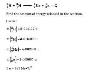
[3 Marks] Diagram 15 – CBSE Class 12 PCM Physics 2025 Set 6 Solutions
Answer: The nuclear density of atomic nuclei, including deuterium and tritium, is a crucial concept in nuclear physics. Nuclear density is defined as the mass of nucleons (protons and neutrons) contained within a given volume. It remains relatively constant across different nuclei regardless of their mass number (A). For example, deuterium has one proton and one neutron, while tritium has one proton and two neutrons. The critical point is that the strong nuclear force binding these nucleons operates over a short range, typically around 2 femtometers. As both deuterium and tritium are isotopes of hydrogen, their nuclear densities are found to be approximately 1017kg/m310^{17} kg/m^3. Hence, the ratio of nucleons to the volume remains the same, illustrating that the nuclear density is fundamentally independent of mass number, A.
Key Points: Nuclear density definition-Nuclear density remains constant for deuterium and tritium-Nuclear force operates over short range-Approximate nuclear density for isotopes is 1017kg/m310^{17} kg/m^3-Binding of nucleons independent of mass number
Question 32.

Define 'self-inductance' of a coil. Derive an expression for self-inductance of a long solenoid of cross-sectional area A and length l, having n turns per unit length.

[3 Marks]
Answer: Self-inductance is a property of a coil that quantifies its ability to oppose changes in electric current. It is defined as the ratio of the induced electromotive force (emf) in the coil to the rate of change of current flowing through it. For a long solenoid, the magnetic field B produced by a current I can be expressed as B = µ₀nI. The total magnetic flux Φ linked with the solenoid is given by Φ = B·A = µ₀nIA. Therefore, the self-inductance L can be derived from the formula L = N(Φ/I), where N is the total number of turns, leading us to L = µ₀n²Al, where n is the number of turns per unit length, A is the cross-sectional area, and l is the length of the solenoid.
Key Points: Definition of self-inductance; Relationship to change in current; Magnetic field in solenoid (B = µ₀nI); Magnetic flux linked with solenoid (Φ = B·A); Derivation using L = N(Φ/I); Final expression for self-inductance (L = µ₀n²Al).

Section E

Question 33.

(i) Write the principle of working of an ac generator. Draw its labelled diagram and explain its working.

(ii) A resistor of 400Ω , an inductor of (5/π) H and a capacitor of (50/π) μF are joined in series across an ac source v = 140 sin (100π )t V. Find the rms voltages across these three circuit elements. The algebraic sum of these voltages is more than the rms voltage of source. Explain.

[5 Marks]
Answer: (i) Principle of AC Generator: An ac generator works on the principle of electromagnetic induction which states that whenever a conductor is moved in a magnetic field, an emf is induced in it. The magnitude of this emf depends on the rate of change of magnetic flux linked with the coil.
Diagram: An ac generator consists of a rectangular coil ABCD mounted on an axle which can rotate about its axis. The coil is placed between the poles of a magnet producing a magnetic field. The ends of the coil are connected to two slip rings which rotate along with the coil. Carbon brushes press against the slip rings to conduct current to an external circuit.
Working: When the coil rotates with an angular velocity omega (ω), the magnetic flux through the coil changes with time. According to Faraday's law, an emf is induced in the coil which varies sinusoidally with time. If theta is the angle between the magnetic field and the normal to the coil, the induced emf is given by e = NABω sin(ωt), where N is number of turns, A is area of the coil, B is magnetic field strength and omega is angular velocity.
Thus, the coil produces alternating emf and hence an alternating current in the external circuit.
(ii) Given Data: Resistance R = 400 Ω, Inductance L = 5/π H, Capacitance C = 50/π μF = (50/(π*10^6)) F, Voltage v = 140 sin(100π t) V, Angular frequency omega = 100π rad/s.
Calculations:
Inductive reactance XL = omega * L = 100π * (5/π) = 500 Ω.
Capacitive reactance XC = 1 / (omega * C) = 1 / (100π * (50/π * 10^-6)) = 1 / (100π * 50/(π * 10^6)) = 1 / (100 * 50 * 10^-6) = 1 / (0.005) = 200 Ω.
Total impedance Z = sqrt(R2 + (XL - XC)2) = sqrt(400^2 + (500 - 200)^2) = sqrt(160000 + 90000) = sqrt(250000) = 500 Ω.
Current I = Vrms / Z = 140 / 500 = 0.28 A.
RMS voltage across resistor VR = I * R = 0.28 * 400 = 112 V.
RMS voltage across inductor VL = I * XL = 0.28 * 500 = 140 V.
RMS voltage across capacitor VC = I * XC = 0.28 * 200 = 56 V.
Explanation: The algebraic sum of the voltages (112 + 140 + 56 = 308 V) is greater than the source voltage (140 V) because these voltages are not in phase; voltage across resistor is in phase with current, voltage across inductor leads current by 90 deg and voltage across capacitor lags current by 90 deg. Hence, they add vectorially and not algebraically, so the resultant voltage matches the source voltage.
Conclusion: Voltage drops across individual components can be greater than source voltage but their vector sum equals the source voltage according to Kirchhoff's voltage law in AC circuits.
Key Points: Principle of electromagnetic induction - Components and working of AC generator - Calculation of reactances, impedance, currents and voltages in RLC series circuit - Explanation of vector addition of voltages in AC circuit
Question 34.

(i) Draw a ray diagram to show the image formation by a compound microscope. Obtain the expression for the total magnification of the microscope when the final image is formed at infinity.

(ii) In a compound microscope, an object is placed at a distance of 1.5 cm from the objective of focal length 1.25 cm. The eyepiece has a focal length of 5 cm. The final image is formed at infinity. Calculate the distance between the objective and the eyepiece.

[5 Marks]
Answer: (i) Ray Diagram: A compound microscope consists of two converging lenses: the objective and the eyepiece. The object is placed just beyond the focal length of the objective lens. The objective lens forms a real, inverted, and magnified image A'B' inside the focal length of the eyepiece. The eyepiece then acts as a simple magnifier and forms the final image A''B'' at infinity.

Derivation of total magnification:
Let fo and fe be the focal lengths of the objective and eyepiece lenses respectively, and D be the least distance of distinct vision (usually 25 cm).
Let mo be the magnification produced by the objective lens = v / u, where u is object distance from objective and v is the image distance from objective.
For final image at infinity, the image formed by the objective acts as an object for the eyepiece at its focal plane.

Magnification by eyepiece, me = D / fe
Total magnification, M = mo * me
Using lens formula for objective: 1/fo = 1/u - 1/v
So, mo = v / u = (L - fe) / u where L is distance between lenses.
When final image is at infinity, L = v + fe approximately.
Combining these, total magnification is
M = (L / fo) * (D / fe)

(ii) Given: u = 1.5 cm, fo = 1.25 cm, fe = 5 cm, D = 25 cm
Find v using lens formula: 1/fo = 1/u - 1/v => 1/1.25 = 1/1.5 - 1/v
=> 1/v = 1/1.5 - 1/1.25 = (0.6667 - 0.8) = -0.1333
=> v = -7.5 cm (Negative sign indicates real image on opposite side)

Distance between objective and eyepiece, L = v + fe = 7.5 + 5 = 12.5 cm

Therefore, the distance between the objective and the eyepiece is 12.5 cm.
Key Points: Ray diagram of compound microscope - Expression for total magnification is M = (L / fo) * (D / fe) when final image is at infinity - Calculation of distance between objective and eyepiece as L = v + fe
Question 35.

(i) The electric field in a region is given by 𝐄⃗ = 40x 𝑖̂ N/C. Find the amount of work done in taking a unit positive charge from a point (0, 3m) to the point (5m, 0).

(ii) A charge Q is distributed over two concentric hollow spheres of radii r and R (> r) such that their surface charge densities are equal. Find :

(I) the electric field, and

(II) the potential

at their common centre.

[5 Marks]
Answer: (i) Given electric field E⃗=40xi^\vec{E} = 40x \hat{i} N/C. Work done in moving charge q from point A(0,3) to B(5,0) is W = q(V_A - V_B). Since q=1 C, W = V_A - V_B. Electric potential difference VB−VA=−∫ABE⃗⋅dl⃗V_B - V_A = -\int_A^B \vec{E} \cdot d\vec{l}. Choose path: from (0,3) to (0,0) along y-axis, then (0,0) to (5,0) along x-axis.
Along y-axis, x=0 so Ex=0E_x = 0 thus no work done.
Along x-axis, E⃗=40xi^\vec{E} = 40x \hat{i}, d\vec{l} = dx \hat{i} \Rightarrow \vec{E} \cdot d\vec{l} = 40x dx.
Potential difference VB−V0=−∫0540xdx=−40imes522=−40imes12.5=−500V_B - V_0 = - \int_0^5 40x dx = - 40 imes \frac{5^2}{2} = - 40 imes 12.5 = -500 V.
Therefore, VB−VA=VB−V0+V0−VA=−500+0=−500V_B - V_A = V_B - V_0 + V_0 - V_A = -500 + 0 = -500 V (since V at (0,0) is 0 along zero path).
Work done W = V_A - V_B = 0 - (-500) = 500 J.

(ii) Given two concentric spheres of radii r and R (R > r) with equal surface charge densities σ\sigma, total charge Q.
Surface area of inner sphere: 4\pi r2, outer sphere: 4\pi R2.
Let charges on inner and outer spheres be Q_r and Q_R respectively.
Since surface charge densities are equal:
σ=Qr4πr2=QR4πR2⇒Qr=QRimesr2R2\sigma = \frac{Q_r}{4\pi r^2} = \frac{Q_R}{4\pi R^2} \Rightarrow Q_r = Q_R imes \frac{r^2}{R^2}.
Total charge: Q=Qr+QR=QR(1+r2R2)=QRR2+r2R2⇒QR=QR2R2+r2Q = Q_r + Q_R = Q_R (1 + \frac{r^2}{R^2}) = Q_R \frac{R^2 + r^2}{R^2} \Rightarrow Q_R = Q \frac{R^2}{R^2 + r^2}.
Similarly, Qr=Qr2R2+r2Q_r = Q \frac{r^2}{R^2 + r^2}.

(I) Electric field at common centre:
By symmetry, electric field inside a charged hollow sphere is zero.
Therefore, net electric field at center due to both spheres is zero.

(II) Potential at center:
Potential due to a sphere of charge Q and radius a at its center is V=KQaV = \frac{K Q}{a}, where K = 9*109 Nm2/C2.
Potential at center from both spheres is sum:
V=KQrr+KQRR=K(Qrr+QRR)V = \frac{K Q_r}{r} + \frac{K Q_R}{R} = K \left( \frac{Q_r}{r} + \frac{Q_R}{R} \right). Substituting Q_r and Q_R:
V=KQ(r2r(R2+r2)+R2R(R2+r2))=KQr+RR2+r2V = K Q \left( \frac{r^2}{r(R^2 + r^2)} + \frac{R^2}{R(R^2 + r^2)} \right) = K Q \frac{r + R}{R^2 + r^2}.

Hence,
Work done = 500 J. Electric field at center = 0. Potential at center = K Q (r + R) / (R2 + r2).
Key Points: Electric field given as function of x - Work done calculated using potential difference and path integration - Charges related by equal surface charge densities - Electric field inside hollow sphere is zero - Potential at center sum of potentials due to each sphere
Question 36.

(i) Obtain an expression for the electric field 𝐄⃗ due to a dipole of diapole moment 𝐩⃗ at a point on its equatorial plane and specify its direction. Hence, find the value of electric field:

(I) at the centre of the dipole (r = 0), and

(II) at a point r >> a,

where 2a is the length of the dipole.

(ii) An electric field 𝐄⃗ = (10x + 5)𝑖̂ N/C exists in a region in which a cube of side L is kept as shown in the figure. Here x and L are in metres. Calculate the net flux through the cube.
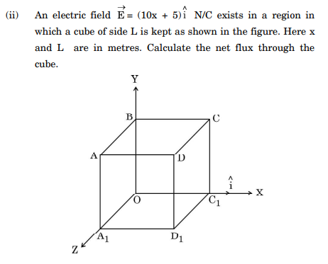
[5 Marks] Diagram 16 – CBSE Class 12 PCM Physics 2025 Set 6 Solutions
Answer: (i) Electric field on the equatorial plane of a dipole:
A dipole consists of charges +q and -q separated by distance 2a. The dipole moment is p = q * 2a directed from -q to +q.
At a point P on the equatorial plane (perpendicular bisector of the dipole axis) at distance r from the centre, the electric field due to +q and -q have same magnitude but direction such that the net electric field is along the axis opposite to the dipole moment.
The magnitude of electric field at equatorial point is given by:
E = - p / (4 * pi * epsilon_0 * r3)
'-' sign indicates the field is opposite to dipole moment direction.
Direction: The electric field is directed opposite to the dipole moment vector on the equatorial plane.
At centre of dipole (r = 0):
The electric field is undefined as field due to point charges diverge. Practically, it can be considered zero because contributions from +q and -q cancel out at centre.
At point r >> a:
Since r is much larger than dipole length, the approximation holds well and electric field magnitude is
E = p / (4 * pi * epsilon_0 * r3)
with direction opposite to dipole moment on equatorial plane.

(ii) Electric flux through the cube:
Given electric field E = (10x + 5) * i N/C, cube side = L meters, and x is coordinate along x-axis.
The net flux through cube surface is given by integral of E dot dA over all faces.
Only faces perpendicular to x contribute as E is along i.
Flux through face at x = L:
Phi1 = E * area = (10L + 5) * L2
Flux through face at x = 0:
Phi2 = (10 * 0 + 5) * L2 = 5 * L2
Net flux, Phi = Phi1 - Phi2 = [(10L + 5) * L2] - [5 * L2] = 10 * L3

Hence, net flux through the cube is 10 * L3 N m2 C-1.
Key Points: Expression for electric field on equatorial plane of dipole - Electric field direction opposite to dipole moment - Net flux calculation using surface integral and Gauss's law
Question 37.

(i) Write the principle of working of a transformer. With the help of a labelled diagram, explain the working of a step-up transformer.

(ii) An ideal transformer is designed to convert 50 V into 250 V. It draws 200 W power from an ac source whose instantaneous voltage is given by v=20 sin (100π) t V.

Find :

(I) rms value of input current.

(II) expression for instantaneous output voltage.

(III) expression for instantaneous output current.

[5 Marks]
Answer: (i) Principle of transformer: A transformer works on the principle of electromagnetic induction which states that a changing magnetic flux in the primary coil induces an emf in the secondary coil.
Working of a step-up transformer: A step-up transformer increases the voltage from primary to secondary. It has more turns in the secondary coil than the primary coil.
When an alternating voltage is applied to the primary coil, it produces an alternating magnetic flux in the iron core. This changing flux links with the secondary coil, inducing an emf according to Faraday's law.
Since the secondary has more turns, the induced emf is greater than the primary voltage, thus stepping up the voltage.
Labelled diagram description: The diagram shows two coils on an iron core; primary connected to input AC, secondary connected to output.

(ii) Given: Vp=50 V, Vs=250 V, power P=200 W, v=20 sin(100 pi t) V.
(I) rms value of input current: rms voltage at input, Vp rms=Vp/sqrt(2)=50/sqrt(2)=35.36 V.
Power P=V I => I = P / Vp rms = 200/35.36 = 5.66 A.
(II) expression for instantaneous output voltage: Since transformer is ideal, voltage ratio = turns ratio = Vs/Vp=250/50=5.
Instantaneous output voltage, vs = 5 * v = 5 * 20 sin(100 pi t) = 100 sin(100 pi t) V.
(III) expression for instantaneous output current: Power input = power output, so Ip rms*Vp rms = Is rms*Vs rms.
Therefore, Is rms = (Vp rms / Vs rms) * Ip rms = (50/250)* 5.66 = 1.13 A.
Instantaneous output current, is = sqrt(2)*Is rms * sin(100 pi t) = 1.13 sqrt(2) sin(100 pi t) = 1.6 sin(100 pi t) A.
Key Points: Principle of electromagnetic induction - Step-up transformer increases voltage by having more turns in secondary coil - Use P=V I relation for current calculations - Instantaneous output voltage = turns ratio * input voltage - Power conservation in ideal transformers for current calculations
Question 38.

(i) Using Huygens principle, explain the refraction of a plane wavefront, propagating in air, at a plane interface between air and glass. Hence verify Snell's law.

(ii) Use mirror formula to deduce that a convex mirror always produces a virtual image of an object kept in front of it.

[5 Marks]
Answer: (i) According to Huygens principle, every point on a wavefront acts as a source of secondary wavelets that spread out in all directions with speed depending on the medium. When a plane wavefront propagates from air to glass, the wavelets travel slower in glass due to its higher refractive index. Consider a plane wavefront AB incident obliquely on the interface between air and glass. Point A reaches the interface first and starts generating secondary wavelets inside the glass, travelling slower with speed v2, while point B is still in air where speed is v1. As a result, the part of the wavefront in glass advances less in the same time compared to the part still in air, causing the wavefront inside glass to bend towards the normal. From geometry, the ratio of sines of the angles of incidence i and refraction r is equal to the ratio of velocities v1/v2. Therefore sin i / sin r = v1 / v2. Since refractive index n = c / v, we get n2 / n1 = v1 / v2. Thus, n1 sin i = n2 sin r, which is Snell's law.
(ii) Mirror formula is given by 1/f = 1/v + 1/u, where f is focal length, v is image distance and u is object distance. For a convex mirror, focal length f is positive and object is placed in front of the mirror making u negative (since distances are measured from mirror). Substituting f > 0 and u < 0 into the equation, we find that the image distance v is always positive but less than f. A positive image distance means the image is formed behind the mirror. This shows that the convex mirror always forms a virtual, erect and diminished image of the object placed in front of it.
Key Points: Huygens principle explains refraction - Wavefront bends towards normal when entering denser medium - Snell's law derived from wave speeds and angles - Mirror formula relates object, image, focal length distances - Convex mirror focal length positive and image formed behind mirror - Convex mirror forms virtual image for real object

Paper Details

CBSE Board Exam 2025

Class

Class 12 PCM

Subject

Physics

Year

2025

Set

Set 6

Other Years — Physics

2022 Set-1

2022 Set-2

2022 Set-3

2022 Set-4

2023 Set-1

2023 Set-2

2023 Set-3

2023 Set-4

2023 Set-5

2024 Set-1

2024 Set-2

2024 Set-3

2024 Set-4

2024 Set-5

2025 Set-1

2025 Set-2

2025 Set-4

2025 Set-5

2025 Set-6

2025 Set-7

CBSE Class 12 Physics 2025 Set 6 Solutions | Prepzy