SOLUTIONS

2023 BOARD EXAM

CBSE Class 12 PCM Physics Board Paper 2023 — Set 5 Solutions

2023

Physics

Class 12 PCM

CBSE EXAMINATION PAPER-2023

PHYSICS

(Solved)

Time allowed : 3 hours

Maximum Marks : 75

General Instructions :

Read the following instructions carefully and follow them :

  1. This question paper contains 44 questions. All questions are compulsory.
  2. This question paper is divided into 5 sections.
  3. Section A – questions number 1 to 4 are case based questions
  4. Section B – questions number 5 to 22 are multiple choice questions
  5. Section C – questions number 23 to 31 are very short answer
  6. Section D – questions number 32 to 38 are short answer
  7. Section E – questions number 39 to 44 are long answer
  8. There is no overall choice given in the question paper. However, an internal choice has been provided in few questions.
  9. Use of calculator is NOT allowed.

Section A

Question 1.
Question 2.

A capacitor is a system of two conductors separated by an insulator. The two conductors have equal and opposite charges with a potential difference between them. The capacitance of a capacitor depends on the geometrical configuration (shape, size and separation) of the system and also on the nature of the insulator separating the two conductors. They are used to store charges. Like resistors, capacitors can be arranged in series or parallel or a combination of both to obtain desired value of capacitance.
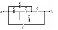
Diagram 1 – CBSE Class 12 PCM Physics 2023 Set 5 Solutions
Question 3. A lens is a transparent optical medium bounded by two surfaces; at least one of which should be spherical. Considering image formation by a single spherical surface successively at the two surfaces of a lens, lens maker’s formula is obtained. It is useful to design lenses of desired focal length using surfaces of suitable radii of curvature. This formula helps us obtain a relation between u, v and f for a lens. Lenses form images of objects and they are used in a number of optical devices, for example microscopes and telescopes.

(1) (ii) A real image of an object formed by a convex lens is observed on a screen

[1 Mark]
Answer: A real image formed by a convex lens can be obtained on a screen because light rays actually converge at the image point. According to the lens formula 1/f = 1/v - 1/u, for a convex lens, when the object is placed beyond the focal length, the image formed is real and inverted and can be projected on a screen, as explained in the case passage.
Key Points: Real image - Convex lens forms real and inverted images when object is beyond focal length - Real images can be obtained on a screen

(2) (i) An object AB is kept in front of a composite convex lens, as shown in figure. Will the lens produce one image ? If not, explain.
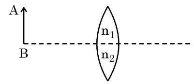
Diagram 2 – CBSE Class 12 PCM Physics 2023 Set 5 Solutions [1 Mark]
Answer: No, the composite convex lens will not produce only one image. Since it is made of two lenses, the image formed by the first lens acts as an object for the second lens, hence two images can be formed as explained in the case where image formation by single spherical surfaces is considered successively.
Key Points: Composite lens formed by two lenses - First image acts as object for second lens - Multiple images possible

(3) (iii) A double convex lens is made of glass of refractive index 1.55 with both faces of the same radius of curvature. Find the radius of curvature required if focal length is 20 cm.

[2 Marks]
Answer: Given the refractive index n = 1.55 and focal length f = 20 cm for a double convex lens with equal radii of curvature R, we use the lens maker’s formula 1/f = (n-1)(1/R1 - 1/R2). Here R1 = R and R2 = -R as one surface is convex and the other concave relative to the light. So, 1/f = (n-1)(1/R - (-1/R)) = 2(n-1)/R. Rearranging, R = 2(n-1)f = 2 * (1.55 - 1) * 20 = 22 cm. So, the radius of curvature required is 22 cm. This shows how the lens maker’s formula helps design lenses of desired focal length using suitable radii, as mentioned in the case passage.
Key Points: Lens maker’s formula relates focal length, refractive index, and radii of curvature - For double convex lens with equal radii, R1 = R and R2 = -R - Radius of curvature can be calculated using R = 2(n-1)f from the formula

(4) (iii) Two convex lenses A and B of focal lengths 15 em and 10 cm respectively are placed coaxially ‘d’ distance apart. A point object is kept at a distance of 30 cm in front of lens A. Find the value of ‘d’ so that the rays emerging from lens B are parallel to its principal axis.

[2 Marks]
Answer: Given two convex lenses A and B with focal lengths 15 cm and 10 cm, an object is placed 30 cm in front of lens A. Using the lens formula 1/f = 1/v - 1/u for lens A, we find its image position v. Here, u = -30 cm (object distance is negative as per sign convention), f = 15 cm. Calculating v for lens A, we get v = 1 / (1/15 + 1/30) = 10 cm. This image acts as an object for lens B, so its object distance for lens B is u_B = d - v = d - 10. For rays to emerge parallel from lens B, image distance v_B = infinity, so object distance u_B = -f_B = -10 cm (using lens formula). Thus, d - 10 = -10 which gives d = 0 cm. Therefore, lenses must be placed so the image from A coincides with B’s focal point. Hence, d = 0 cm. This solution uses the lens formula from the case passage and the concept that parallel rays emerge when object is at focal point.
Key Points: Use of lens formula 1/f = 1/v - 1/u - Image by lens A acts as object for lens B - For rays to be parallel after lens B, object must be at its focal length on the left side
Question 4. A capacitor is a system of two conductors separated by an insulator. The two conductors have equal and opposite charges with a potential difference between them. The capacitance of a capacitor depends on the geometrical configuration (shape, size and separation) of the system and also on the nature of the insulator separating the two conductors. They are used to store charges. Like resistors, capacitors can be arranged in series or parallel or a combination of both to obtain desired value of capacitance.

(1) (i) Find the equivalent capacitance between points A and B in the given diagram.
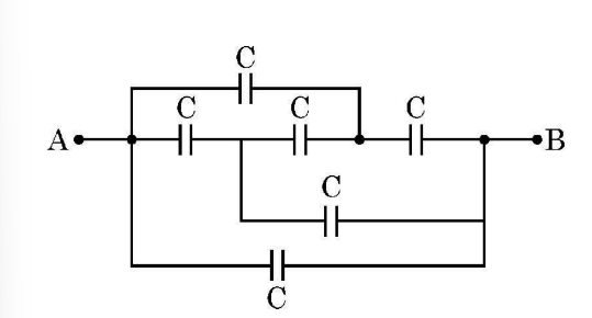
Diagram 3 – CBSE Class 12 PCM Physics 2023 Set 5 Solutions [1 Mark]
Answer: The equivalent capacitance between points A and B can be found by first calculating the capacitance of capacitors C1, C2, and C3 connected in series, then adding it in parallel with capacitor C4, as capacitors in series have reciprocal capacitances added and capacitors in parallel have their capacitances summed. This method is based on the principle that capacitance depends on system configuration as mentioned in the case.
Key Points: Equivalent capacitance depends on capacitor arrangement - Series capacitances add reciprocally - Parallel capacitances add directly

(2) (iv) Two slabs of dielectric constants 2K and K fill the space between the plates of a parallel plate capacitor of plate area A and plate separation d as shown in figure. Find an expression for capacitance of the system.
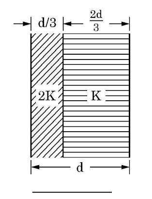
Diagram 4 – CBSE Class 12 PCM Physics 2023 Set 5 Solutions [1 Mark]
Answer: When two dielectric slabs with dielectric constants 2K and K are placed between the plates, they form two capacitors in series with thickness d/2 each. The capacitance of each slab is C1 = 2KA*epsilon_0/(d/2) and C2 = K*A*epsilon_0/(d/2). The total capacitance C is given by 1/C = 1/C1 + 1/C2. Substituting, we get the expression for capacitance considering the two slabs.
This uses the principle from the case that capacitance depends on the insulator separating the conductors.
Key Points: Capacitor consists of two conductors separated by insulator - Capacitance depends on dielectric constant and geometry - Two dielectrics in series act as capacitors in series

(3) (iii) A capacitor A of capacitance C, having charge Q is connected across another uncharged capacitor B of capacitance 2C. Find an expression for (a) the potential difference across the combination and (b) the charge lost by capacitor A.

[2 Marks]
Answer: When capacitor A (capacitance C) with charge Q is connected to uncharged capacitor B (capacitance 2C), charge redistributes until both capacitors have the same potential difference, as charges flow through the connection. Let the final potential difference be V. Initially, voltage on A is V = Q / C. Total charge is Q, which is now shared. Total capacitance after connection is C + 2C = 3C. So, V = Q / 3C. Charge on capacitor A after connection is Q_A = C * V = C * (Q / 3C) = Q / 3. Charge lost by A is initial charge minus final charge = Q - Q / 3 = 2Q / 3. This solution uses the formula for capacitance and charge from the case paragraph.
Key Points: Capacitance depends on geometry and insulator - Charge redistributes to equalize potential difference - Total charge is conserved but charges on individual capacitors change

(4) A dielectric slab is inserted between the plates of a parallel plate capacitor. The electric field between the plates decreases. Explain.

[1 Mark]
Answer: When a dielectric slab is inserted between the plates of a capacitor, it reduces the effective electric field between the plates because the dielectric gets polarized and creates an opposing field. This decreases the potential difference for the same charge, increasing the capacitance as explained in the case passage where capacitance depends on the nature of the insulator.
Key Points: Dielectric reduces electric field - Dielectric gets polarized creating opposing field - Capacitance depends on insulator nature

Section B

Question 5.

An electric dipole of length 2 cm is placed at an angle of 30° with an electric field 2 x 10^5 N/C. If the dipole experiences a torque of 8 x 10^⁻3 Nm, the magnitude of either charge of the dipole, is:

[1 Mark]
  • (A) 8 mC
  • (B) 7 μC
  • (C) 2 mC
  • (D) 4 μC
Explanation: To find the magnitude of either charge of the dipole (p), we use the formula for torque (τ) in an electric field (E): τ = pE sin(θ). Given τ = 8 x 10^-3 Nm, E = 2 x 10^5 N/C, and θ = 30°, we first calculate sin(30°) = 0.5. The length of the dipole (d) is 2 cm = 0.02 m. Therefore, p = τ / (E sin(θ)) = (8 x 10^-3) / (2 x 10^5 * 0.5) = 8 x 10^-3 / 10^5 = 8 x 10^-8 C*m. The magnitude of either charge is q = p / (d) = (8 x 10^-8) / (0.02) = 4 x 10^-6 C = 4 μC.
Question 6.

Two long parallel wires kept 2 m apart carry 3A current each, in the same direction. The force per unit length on one wire due to the other is:

[1 Mark]
  • (A) 9 x 10⁻⁷ N/m, repulsive
  • (B) 4.5 x 10⁻⁷ N/m, repulsive
  • (C) 9 x 10^⁻5 N/m, attractive
  • (D) 4.5 x 10^⁻5 N/m, attractive
Explanation:

When two parallel wires carry currents in the same direction, they experience an attractive force due to the magnetic fields generated by their currents. The formula for the force per unit length between two parallel currents is given by F/L = (μ₀/2π) * (I₁ * I₂) / d, where μ₀ is the permeability of free space, I₁ and I₂ are the currents in the wires, and d is the distance between them. For currents of 3A each and a distance of 2m apart, the force per unit length calculates to be 4.5 x 10⁻⁷ N/m, and since the currents are in the same direction, the force is attractive.

Question 7.

Which of the following has its permeability less than that of free space?

[1 Mark]
  • (A) Aluminium
  • (B) Copper chloride
  • (C) Nickel
  • (D) Copper
Explanation:

Aluminium has its permeability less than that of free space, making it the correct answer. The other materials listed, such as Copper chloride, Nickel, and Copper, do not have this property.

Question 8.

A square shaped coil of side 10 cm, having 100 turns is placed perpendicular to a magnetic field which is increasing at 1 T/s. The induced emf in the coil is:

[1 Mark]
  • (A) 0.5 V
  • (B) 1 V
  • (C) 0.75 V
  • (D) 0.1 V
Explanation:

Using Faraday's law of electromagnetic induction, the induced emf (E) in the coil can be calculated using the formula E = -N * (dΦ/dt), where N is the number of turns and dΦ/dt is the rate of change of magnetic flux. The area (A) of the square coil is (0.1 m * 0.1 m) = 0.01 m². The magnetic flux (Φ) is given by B * A, so dΦ/dt = A * (dB/dt) = 0.01 m² * 1 T/s = 0.01 V. Therefore, the induced emf E = 100 * 0.01 V = 1 V. The correct answer is 1 V.

Question 9. Which one of the following electromagnetic radiation has the least wavelength?
[1 Mark]
  • (A) Microwaves
  • (B) Gamma rays
  • (C) Visible light
  • (D) X-rays
Explanation: Gamma rays have the least wavelength among the options provided. In the electromagnetic spectrum, wavelengths decrease from radio waves to gamma rays, with gamma rays having the shortest wavelengths and the highest energy.
Question 10.

In a Young's double-slit experiment, the screen is moved away from the plane of the slits. What will be its effect on the following?

(A) Angular separation of the fringes.

(B) Fringe-width.

[1 Mark]
  • (A) Both (A) and (B) increase.
  • (B) Both (A) and (B) remain constant.
  • (C) (A) remains constant, but (B) increases.
  • (D) (A) remains constant, but (B) decreases.
Explanation: When the screen is moved away from the plane of the slits, the fringe-width increases because fringe-width is directly proportional to the distance from the slits to the screen. However, the angular separation of the fringes remains constant since it depends only on the slit separation and the wavelength of light used.
Question 11.

The energy of a photon of wavelength λ is:

[1 Mark]
  • (A) λ/hc
  • (B) hc λ
  • (C) λh/c
  • (D) hc/λ
Explanation: The correct option is hc/λ because the energy (E) of a photon is directly related to its wavelength (λ) through the equation E = hc/λ, where h is Planck's constant and c is the speed of light. This formula shows that as the wavelength decreases, the energy increases, making hc/λ the correct expression for the energy of a photon.
Question 12.

The ratio of the nuclear densities of two nuclei having mass numbers 64 and 125 is:

[1 Mark]
  • (A) 0.8
  • (B) 0.512
  • (C) 1
  • (D) 1.25
Explanation:

The nuclear density of different nuclei is generally constant, as it is largely independent of mass number. Therefore, when comparing two nuclei with different mass numbers, the ratio of their densities will essentially be 1. This is because both nuclei occupy a similar volume per nucleon despite their differing mass numbers.

Question 13.

During the formation of a p-n junction:

[1 Mark]
  • (A) Drift current remains constant.
  • (B) Both the diffusion current and drift current remain constant.
  • (C) Diffusion current remains almost constant but drift current increases till both currents become equal.
  • (D) Diffusion current keeps increasing.
Explanation: Diffusion current remains almost constant but drift current increases till both currents become equal. This happens because, as the p-n junction forms, holes from the p-side diffuse into the n-side and electrons from the n-side diffuse into the p-side, which creates a diffusion current. As the charge carriers recombine, an electric field develops, leading to a drift current that increases until it balances the diffusion current.
Question 14.

The diagram shows four energy levels of an electron in the Bohr model of hydrogen atom. Identify the transition in which the emitted photon will have the highest energy.
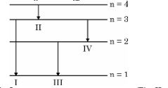
[1 Mark] Diagram 5 – CBSE Class 12 PCM Physics 2023 Set 5 Solutions
  • (A) I
  • (B) III
  • (C) IV
  • (D) II
Explanation:

The highest energy photon is emitted during the transition from the highest energy level (n=4) to the lowest energy level (n=1), which corresponds to option IV. This is because the energy of a photon is directly related to the difference in energy levels; the greater the difference, the higher the energy of the emitted photon.

Question 15.

Which of the following graphs correctly represents the variation of a particle's momentum with its associated de-Broglie wavelength?
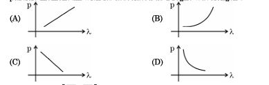
[1 Mark] Diagram 6 – CBSE Class 12 PCM Physics 2023 Set 5 Solutions
  • (A) Step function
  • (B) Inversely proportional
  • (C) Quadratic
  • (D) Linear
Explanation:

The correct option is 'Inversely proportional'. According to the de-Broglie hypothesis, the momentum (p) of a particle is inversely proportional to its wavelength (λ), which is expressed by the formula p = h/λ, where h is Planck's constant. This indicates that as the wavelength increases, the momentum decreases, hence their relationship is inversely proportional.

Question 16.

The capacitors, each of 4 μF are to be connected in such a way that the effective capacitance of the combination is 6 µF. This can be achieved by connecting

[1 Mark]
  • (A) Two of them connected in series and the combination in parallel to the third.
  • (B) All three in series
  • (C) All three in parallel
  • (D) Two of them connected in parallel and the combination in series to the third.
Explanation:

The correct option is 'Two of them connected in parallel and the combination in series to the third.' Connecting two capacitors in parallel adds their capacitances, yielding 4 μF + 4 μF = 8 μF. Then, connecting the resulting 8 μF in series with the third 4 μF capacitor gives an effective capacitance of 1/(1/8 + 1/4) = 6 μF.

Question 17.

Assertion (A): The resistance of an intrinsic semiconductor decreases with increase in its temperature.

Reason (R): The number of conduction electrons as well as holes increase in an intrinsic semiconductor with a rise in its temperature.

[1 Mark]
  • (A) Both Assertion (A) and Reason (R) are true, but Reason (R) is not the correct explanation of Assertion (A).
  • (B) Both Assertion (A) and Reason (R) are true and Reason (R) is the correct explanation of Assertion (A).
  • (C) Both Assertion (A) and Reason (R) are false.
  • (D) Assertion (A) is true, but Reason (R) is false.
Explanation: Both Assertion (A) and Reason (R) are true and Reason (R) is the correct explanation of Assertion (A). As the temperature of an intrinsic semiconductor increases, more electrons gain enough energy to break free from their atomic bonds, leading to an increase in both conduction electrons and holes. This increase in charge carriers results in a decrease in resistance.
Question 18.

Assertion (A): The equivalent resistance between points A and B in the given network is 2R. Reason (R): All the resistors are connected in parallel.
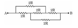
[1 Mark] Diagram 7 – CBSE Class 12 PCM Physics 2023 Set 5 Solutions
  • (A) Both Assertion (A) and Reason (R) are true and Reason (R) is the correct explanation of Assertion (A).
  • (B) Both Assertion (A) and Reason (R) are true, but Reason (R) is not the correct explanation of Assertion (A).
  • (C) Assertion (A) is true, but Reason (R) is false.
  • (D) Both Assertion (A) and Reason (R) are false.
Explanation:

The assertion A states that the equivalent resistance is 2R, but this is likely incorrect if all resistors are connected in parallel. In a parallel connection, the overall resistance is generally less than the smallest individual resistor. Therefore, the reason R is false, which makes the assertion A also false regarding the provided context.

Question 19.

Assertion (A): The deflecting torque acting on a current carrying loop is zero when its plane is perpendicular to the direction of the magnetic field.

Reason (R): The deflecting torque acting on a loop of magnetic moment m in a magnetic field B is given by the dot product of m and B.

[1 Mark]
  • (A) Both Assertion (A) and Reason (R) are false.
  • (B) Both Assertion (A) and Reason (R) are true and Reason (R) is the correct explanation of Assertion (A).
  • (C) Assertion (A) is true, but Reason (R) is false.
  • (D) Both Assertion (A) and Reason (R) are true, but Reason (R) is not the correct explanation of Assertion (A).
Explanation:

Assertion (A) is true because when the plane of the loop is perpendicular to the magnetic field, the angle between the magnetic moment and the magnetic field is 90 degrees, leading to zero torque. Reason (R) is also true as it correctly states that the torque is determined by the dot product of the magnetic moment and the magnetic field. However, Reason (R) does not directly explain Assertion (A), as it merely describes the relationship without addressing the specific case of zero torque. Therefore, the correct option is that both are true, but R is not the correct explanation of A.

Question 20. According to Huygens principle, the amplitude of secondary wavelets is:
[1 Mark]
  • (A) Maximum in the forward direction and zero in the backward direction.
  • (B) Equal in both the forward and the backward directions.
  • (C) Small in the forward direction and large in the backward direction.
  • (D) Large in the forward direction and small in the backward direction.
Explanation: The correct answer is 'Maximum in the forward direction and zero in the backward direction.' According to Huygens' principle, each point on a wavefront can be considered a source of secondary wavelets that spread out in all directions. However, the intensity and amplitude of these wavelets are greater in the forward direction (where the wave is propagating) and diminish in the backward direction, effectively becoming zero.
Question 21. The radius of the nth orbit in the Bohr model of the hydrogen atom is proportional to:
[1 Mark]
  • (A) n²
  • (B) 1/n²
  • (C) n
  • (D) 1/n
Explanation: The radius of the nth orbit in the Bohr model is given by the formula r_n = n² * r_0, where r_0 is the radius of the first orbit. This shows that the radius is proportional to n², making option 'n²' the correct answer.
Question 22.

Which of the following statements about a series LCR circuit connected to an ac source is correct ?

[1 Mark]
  • (A) If the frequency of the source is increased, the impedance of the circuit first decreases and then increases.
  • (B) If the net reactance (XL -XC) of circuit becomes equal to its resistance, then the current leads the voltage by 45°.
  • (C) At resonance, the voltage drop across the inductor is more than that across the capacitor.
  • (D) At resonance, the voltage drop across the capacitor is more than that across the inductor.
Explanation:

At resonance, the reactance of the inductor (XL) equals the reactance of the capacitor (XC), resulting in the impedance being purely resistive. Consequently, the voltage drops across the inductor and capacitor become equal, but their phase is opposite. Thus, the statement 'At resonance, the voltage drop across the capacitor is more than that across the inductor' is not true. Instead, the correct understanding of resonance aligns with the behavior of the circuit's impedance and the relationships between voltage and reactance. Correct answer is If the frequency of the source is increased, the impedance of the circuit first decreases and then increases.

Section C

Question 23.

(a) How will the de Broglie wavelength associated with an electron be affected when (i) the velocity of the electron decreases? and (ii) accelerating potential is increased ? Justify your answer.

[2 Marks]
Answer: The de Broglie wavelength is given by λ = h/p, where h is Planck's constant and p is the momentum (p = mv). (i) If the velocity of the electron decreases, its momentum decreases, leading to an increase in the de Broglie wavelength. (ii) Increasing the accelerating potential increases the velocity of the electron, resulting in higher momentum and a decrease in the de Broglie wavelength. Thus, the wavelength is directly related to the velocity of the electron.
Key Points: de Broglie wavelength formula; relationship between momentum and velocity; decreasing velocity increases wavelength; increasing potential increases velocity and decreases wavelength.
Question 24.

Identify the electromagnetic wave whose wavelength range is from about

(a) 10^-12 m to about 10^-8 m.

(b) 10^-3 m to about 10^-1 m.

Write one use of each.

[2 Marks]
Answer: The electromagnetic wave with a wavelength range of approximately 10^-12 m to 10^-8 m is gamma rays. They are used in cancer treatment to kill cancerous cells. For the range of 10^-3 m to 10^-1 m, microwaves are present, which are commonly used in microwave ovens for cooking food. Both types of waves are essential in various technologies and medical applications.
Key Points: Gamma rays; used in cancer treatment - Microwaves; used in cooking
Question 25.

Depict the orientation of an electric dipole in (a) stable and (b) unstable equilibrium in an external uniform electric field. Write the potential energy of the dipole in each case.

[2 Marks]
Answer: In a stable equilibrium, the electric dipole aligns with the external electric field, minimizing potential energy. The orientation is such that the positive charge faces the field. In contrast, in an unstable equilibrium, the dipole is positioned opposite to the field, maximizing potential energy. The potential energy (U) of the dipole is given by U = -p·E cos(θ), where θ is the angle between dipole moment (p) and the field (E). In stable equilibrium, θ = 0°, and in unstable, θ = 180°.
Key Points: Stable equilibrium where dipole aligns with field; Unstable equilibrium where dipole is anti-parallel to field; Potential energy formula U = -p·E cos(θ); U is minimum (negative) in stable and maximum (positive) in unstable.
Question 26.

(b) A long straight wire AB carries a current I. A particle (mass m and charge q) moves with a velocity v, parallel to the wire, at a distance d from it as shown in the figure. Obtain the expression for the force experienced by the particle and mention its directions.
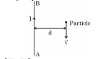
[2 Marks] Diagram 8 – CBSE Class 12 PCM Physics 2023 Set 5 Solutions
Answer: The force experienced by a charged particle moving in a magnetic field can be described by the equation F = q(v × B). Here, B is the magnetic field produced by the wire, calculated as B = (μ0I)/(2πd). Substituting this into our equation gives F = qv(μ0I)/(2πd). The direction of the force can be determined using the right-hand rule: it will be perpendicular to both the velocity of the particle and the magnetic field direction.
Key Points: Use of F = q(v × B) - Calculation of B using B = (μ0I)/(2πd) - Expression for F as qvB - Direction determined by the right-hand rule
Question 27.

Draw a graph showing the variation of potential energy of a pair of nucleons as a function of their separation. Indicate the region in which the nuclear force is (a) attractive and (b) repulsive.

[2 Marks]
Answer: The graph of potential energy (U) versus separation distance (r) of a pair of nucleons typically shows a curve starting from positive potential energy at large separations, decreasing to negative values, and then increasing again. In the region where nucleons are close together (approximately 0.5 to 1.2 femtometers), the nuclear force is attractive, indicated by the negative potential energy. When nucleons are extremely close (less than 0.5 femtometers), the potential energy rises sharply, showing the repulsive force. Hence, attractive forces dominate at intermediate separations, while repulsive forces prevail at very short separations.
Key Points: Graph of potential energy vs. separation, Negative potential energy indicates attraction, Positive potential energy indicates repulsion, Attractive forces at 0.5 to 1.2 femtometers, Repulsive forces below 0.5 femtometers.
Question 28.

The potential difference applied across a given conductor is doubled. How

will this affect (i) the mobility of electrons and (ii) the current density in

the conductor ? Justify your answers.

[2 Marks]
Answer: Doubling the potential difference across a conductor increases the electric field. This results in a greater force acting on the charge carriers, specifically electrons, thereby increasing their mobility. However, the mobility of electrons primarily depends on temperature and the material properties, so it may not be significantly affected. On the other hand, current density, defined as current per unit area, will increase due to a higher potential difference, according to Ohm's law (J = σE, where J is current density, σ is conductivity, and E is electric field).
Key Points: Increased electric field; higher mobility of electrons; mobility primarily temperature-dependent; increased current density according to Ohm's law.
Question 29.

Two coils C1, and C2, are placed close to each other. The magnetic flux φ2 linked with the coil C2, varies with the current I1, flowing in coil C1, as

shown in the figure. Find

(i) the mutual inductance of the arrangement, and

(ii) the rate of change of current (dI1/dt) that will induce an emf of 100 V

in coil C2.
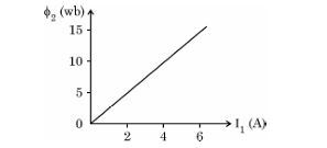
[2 Marks] Diagram 9 – CBSE Class 12 PCM Physics 2023 Set 5 Solutions
Answer: To find the mutual inductance (M), we use the formula φ2 = M * I1, where φ2 is the magnetic flux linked with C2. By rearranging, M = φ2 / I1. For the given scenario, we need to calculate the appropriate values from the figure provided. To induce an emf of 100 V in coil C2, we apply Faraday's law of electromagnetic induction: emf = -M * (dI1/dt). Rearranging gives (dI1/dt) = emf / M. Thus, we can compute both M and (dI1/dt).
Key Points: Use the relation between flux and mutual inductance; Employ Faraday's law for emf calculation; Rearrange formulas to find values.
Question 30.

(b) How would the stopping potential for a given photosensitive surface change if (i) the frequency of the incident radiation were increased ? and (i) the intensity of incident radiation were decreased ? Justify your answer.

[2 Marks]
Answer: Increasing the frequency of incident radiation increases the stopping potential for a given photosensitive surface. This is because a higher frequency corresponds to higher energy photons, which can eject electrons with greater kinetic energy. Conversely, decreasing the intensity of incident radiation does not affect the stopping potential, as the stopping potential is independent of intensity. It remains the same regardless of the number of photons present, as long as the frequency remains constant.
Key Points: stopping potential increases with frequency; stopping potential is independent of intensity; higher frequency means higher photon energy; intensity affects photocurrent but not stopping potential
Question 31.

(a) Write the expression for the Lorentz force on a particle of charge q moving with a velocity V in a magnetic field B. When is the magnitude of this force maximum ? Show that no work is done by

this force on the particle during its motion from a point r1, to point r2.

[2 Marks]
Answer: The Lorentz force on a particle of charge q moving with velocity v in a magnetic field B is given by F = q(v × B). The magnitude of this force is maximum when the velocity vector is perpendicular to the magnetic field, resulting in sin(θ) = 1, where θ is the angle between v and B. Since the Lorentz force is always perpendicular to the motion, it does no work on the particle when moving from r1 to r2.
Key Points: Lorentz force: F = q(v × B) - Maximum force when v is perpendicular to B - No work done due to perpendicular force

Section D

Question 32.

(a) A plane wave-front propagating in a medium of refractive index ‘μ1, is incident on a plane surface making an angle of incidence (i). It enters into a medium of refractive index μ2(μ2>μ1).

Use Huygen’s construction of secondary wavelets to trace the retracted wave-front. Hence verify Snell’s law of refraction.

[3 Marks]
Answer: To illustrate Huygen's principle for reflection, consider an incident wave-front striking a reflective surface at an angle of incidence 'i'. According to Huygen’s construction, every point on the incident wave-front acts as a source of secondary wavelets. The new wave-front can be traced by drawing tangents to these wavelets. For reflection, the angle of incidence (i) equals the angle of reflection (r). This verifies the law of reflection: i = r. Each secondary wavelet shows that the angle measures are equal, confirming that the wave-front reflects symmetrically about the normal.
Key Points: Huygen's principle; incident wave-front; angle of incidence; secondary wavelets; reflected wave-front; law of reflection; angles i and r
Question 33.

An alternating voltage of 220 V is applied across a device X. A current of 0.22 A flows in the circuit and it lags behind the applied voltage in phase

by π/2 radian. When the same voltage is applied across another device Y,

the current in the circuit remains the same and it is in phase with the

applied voltage.

(i) Name the devices X and Y and,

(ii) Calculate the current flowing in the circuit when the same voltage is

applied across the series combination of X and Y.

[3 Marks]
Answer: Device X is a capacitor, as indicated by the current lagging the voltage by π/2 radians, while device Y is a resistor, given that the current is in phase with the voltage. For the series combination of both devices, the total impedance (Z) of the circuit is calculated. Since the current through devices X and Y is the same, the total voltage across both devices remains 220 V. Thus, the effective current when both are in series remains at 0.22 A as the capacitor and resistor affect the voltage but not the current in series. The overall current in the circuit remains the same at 0.22 A.
Key Points: Device X is a capacitor; Device Y is a resistor; Voltage in series is 220 V; Current remains at 0.22 A.
Question 34.

State the basic principle behind the working of an ac generator. Briefly describe its working and obtain the expression for the instantaneous value of emf induced.

[3 Marks]
Answer: The basic principle behind the working of an AC generator is electromagnetic induction, as described by Faraday's law. An AC generator consists of a rotating coil placed in a magnetic field. When the coil rotates, it cuts across magnetic field lines, inducing an electromotive force (emf) in the coil due to changing magnetic flux. The emf generated is alternating because the direction of the induced current changes with the rotation of the coil. The instantaneous value of the induced emf (E) can be expressed as E = E₀ sin(ωt), where E₀ is the maximum emf, ω is the angular frequency, and t is time.
Key Points: Electromagnetic induction principle - Rotating coil in magnetic field - Induces alternating emf - Changes direction based on coil rotation - Instantaneous emf expression: E = E₀ sin(ωt)
Question 35.

(a) Briefly describe how the current sensitivity of a moving coil galvanometer can be increased.

(b) A galvanometer shows full scale deflection for current Ig,. A resistance

R1, is required to convert it into a voltmeter of range (0 — V) and a

resistance R2, to convert it into a voltmeter of range (0 — 2V). Find the

resistance of the galvanometer.

[3 Marks]
Answer: To increase the current sensitivity of a moving coil galvanometer, one can use several methods. First, increasing the number of turns in the coil enhances sensitivity since it augments the torque produced per unit current. Second, using a stronger magnetic field increases the deflection for the same current. Third, reducing the moment of inertia of the coil allows quicker responses to current changes. As for the resistance of the galvanometer (Rg), let's assume that the voltmeter requires certain resistances R1 and R2 for different ranges. The voltmeter resistance R1 can be expressed as R1 = (V/Ig) - Rg. Similarly, for R2, R2 = (2V/Ig) - Rg. Consequently, by solving these equations, we can determine Rg based on the desired voltage outputs.
Key Points: Increasing coil turns increases sensitivity; stronger magnetic field enhances torque; reducing moment of inertia improves response time; Rg = (V/Ig) - R1; Rg = (2V/Ig) - R2; solving equations gives Rg.
Question 36.

(a) (i) Differentiate between ‘distance of closest approach’ and ‘impact

parameter’.

(ii) Determine the distance of closest approach when an alpha particle of kinetic energy 3.95 MeV approaches a nucleus of Z = 79, stops and reverses its directions.

[3 Marks]
Answer: The distance of closest approach is the minimum distance between the alpha particle and the nucleus during a head-on collision, where all kinetic energy converts to potential energy, while the impact parameter is the perpendicular distance from the trajectory of the incoming particle to the center of the nucleus. For an alpha particle with kinetic energy 3.95 MeV approaching a nucleus of Z = 79, the distance of closest approach can be calculated using the formula: 1.44 × Z × (1.6 × 10^{-19}) / KE, yielding approximately 3.48 femtometers.
Key Points: Distance of closest approach is minimum distance during collision; impact parameter is perpendicular distance from trajectory to nucleus; use formula for distance of closest approach for KE calculation; answer includes numerical example for alpha particle and nucleus.
Question 37.

(b) Using Huygen’s construction, show how a plane wave is reflected from a surface. Hence verify the law of reflection.

[3 Marks]
Answer: Huygens' construction illustrates how each point on a wavefront acts as a new source of secondary wavelets. For a plane wave incident on a reflecting surface, consider the incident wavefront AB striking surface PP'. According to Huygens' principle, each point along AB generates wavelets that propagate outward. At the moment of reflection, these wavelets form a new wavefront CE, which is also planar. The angles between the incident wavefront and the normal to the surface (angle of incidence) and the reflected wavefront and the normal (angle of reflection) are equal, thus verifying the law of reflection, i.e., angle i = angle r.
Key Points: Huygens' principle; plane wave interaction; secondary wavelets; incident wavefront AB; reflection wavefront CE; angles of incidence and reflection; law of reflection verification.
Question 38.

(b) (i) State three postulates of Bohr’s theory of hydrogen atom.

(ii) Find the angular momentum of an electron revolving in the second orbit in Bohr’s hydrogen atom.

[3 Marks]
Answer: Bohr's theory of the hydrogen atom is based on three fundamental postulates. Firstly, electrons revolve around the nucleus in specific, stable orbits without emitting energy, which are known as stationary states. Secondly, these orbits are quantized; meaning the angular momentum of an electron in these orbits is an integral multiple of h/2πh/2\pi (where hh is Planck’s constant). Thirdly, an electron can transition between orbits by absorbing or emitting energy in discrete amounts. To find the angular momentum of an electron in the second orbit, we use the formula L=nh/2πL = nh/2\pi. For the second orbit, n=2n = 2, leading to L=2h/2π=h/πL = 2h/2\pi = h/\pi.
Key Points: Electrons revolve in specific, stable orbits without energy emission-Angular momentum is quantized as an integral multiple of h/2π-Energy transitions involve discrete amounts of energy

Section E

Question 39.

(a) (i) Explain how free electrons in a metal at constant temperature attain an average velocity under the action of an electric field. Hence obtain an expression for it.

(ii) Consider two conducting wires A and B of the same diameter but made of different materials joined in series across a battery. The number density of electrons in A is 1.5 times that in B. Find the ratio of drift velocity of electrons in wire A to that in wire B.

[3 Marks]
Answer: Under the influence of an electric field, free electrons in a metal gain kinetic energy and start moving in the direction opposite to the electric field. Due to frequent collisions with lattice ions and impurities, these electrons maintain a certain average drift velocity, termed the drift velocity (v_d). The average drift velocity can be derived from the equation: v_d = (eEτ)/(m). Here, e is the charge of the electron, E is the electric field strength, τ is the average time between collisions, and m is the mass of the electron. If wire A has number density n_A and wire B has n_B, where n_A = 1.5n_B, the ratio of drift velocities can be given by: v_d,A/v_d,B = (n_B/n_A) = 1/1.5 = 2/3. Thus, this demonstrates the relationship between charge carrier density and drift velocity in conductors.
Key Points: Application of electric field, free electron motion, average drift velocity, expression for drift velocity (v_d = eEτ/m), comparison of number density of electrons, derivation of drift velocity ratio.
Question 40.

(a) Draw the circuit arrangement for studying V-I characteristics of a p-n junction diode in (i) forward biasing and (ii) reverse biasing. Draw the typical V-I characteristics of a silicon diode. Describe briefly the following terms : (i) minority carrier injection in forward biasing and (ii) breakdown voltage in reverse biasing.

[3 Marks]
Answer: To study the V-I characteristics of a p-n junction diode, we arrange the circuit with a variable resistor and a voltmeter connected in parallel across the diode. For forward biasing, the anode is connected to the positive terminal of the power source and in reverse biasing, the cathode connects to the positive terminal. The V-I graph typically shows a threshold voltage around 0.7V for silicon, then a steep rise in current in forward bias, and negligible current in reverse until breakdown occurs. Minority carrier injection happens in forward bias, where electrons from the n-type region are injected into the p-type, allowing conduction. In reverse bias, the breakdown voltage is the point where the diode conducts significantly in reverse due to high electric field ionizing the junction, which can lead to permanent damage if not controlled.
Key Points: circuit arrangement for V-I characteristics in forward and reverse bias, V-I characteristics graph of silicon diode, explanation of minority carrier injection and its role, definition of breakdown voltage and its implications
Question 41.

(a) (i) Draw a ray diagram to show the working of a compound microscope. Obtain the expression for the total magnification for the final image to be formed at the near point.

(ii) In a compound microscope an object is placed at a distance of 1.5 cm from the objective of focal length 1.25 cm. If the eye-piece has a focal length of 5 cm and the final image is formed at the near point, find the magnifying power of the microscope.

[3 Marks]
Answer: To illustrate the working of a compound microscope, we begin by drawing a ray diagram showing the objective and eyepiece. The objective lens, when an object is placed at a distance of 1.5 cm, produces a real, inverted image at a distance further away from it. This image then acts as the object for the eyepiece which produces a virtual image that is viewed at the near point. The total magnification (M) is given by the formula M = mo * me, where mo = L / f0 and me = L / fe, with L being the near point distance, f0 the focal length of the objective lens, and fe the focal length of the eyepiece. Substituting the values provided: f0 = 1.25 cm, fe = 5 cm and L = 25 cm (assuming it is standard near point), we compute magnification to be M = (25/1.25) * (25/5) = 125.
Key Points: 1. Ray diagram showing objective and eyepiece, 2. Formula for total magnification M = mo * me, 3. Calculation of magnification using given values (object distance, focal lengths)
Question 42.

(b) (i) A cell emf of (E) and internal resistance (r) is connected across a variable load resistance (R). Draw plots showing the variation of terminal voltage V with (i) R and (ii) the current (I) in the load.

(ii) Three cells, each of emf E but internal resistances 2r, 3r and 6r

are connected in parallel across a resistor R.

Obtain expressions for (i) current flowing in the circuit, and (ii) the terminal potential difference across the equivalent cell.

[3 Marks]
Answer: To analyze the system, we first examine the terminal voltage (V) across the variable load resistance (R) connected to a cell of emf (E) and internal resistance (r). The terminal voltage can be expressed as V = E - Ir, where I is the current flowing through the circuit. The first graph illustrates the relationship between V and R, showcasing that as R increases, V approaches E, while current (I) decreases. The second graph illustrates how as the load current (I) increases (due to decreasing R), terminal voltage (V) decreases due to the potential drop across the internal resistance (r). For three parallel cells with internal resistances 2r, 3r, and 6r, the equivalent internal resistance (req) can be calculated using the formula 1/req = 1/(2r) + 1/(3r) + 1/(6r), yielding req = 1.2r. The total emf remains E. Hence, the total current (I_total) can be expressed as I_total = E/req = E/(1.2r) = (5/6)(E/r). Lastly, the terminal potential difference across the equivalent cell is V_eq = E - I_total * req = E - (5/6)(E/r) * (1.2r) = E(1 - 1) = 0, showing losses in potential across internal resistances.
Key Points: Terminal voltage relation - V = E - Ir; Influence of variable load R on V and I; Graphs of V vs. R and I; Three cells in parallel - req = 1.2r; Current in circuit - I_total = 5E/(6r); Terminal potential across equivalent - V_eq computation
Question 43.

(b) Name two important processes involved in the formation of a p-n

junction diode. With the help of a circuit diagram, explain the working of junction diode as a full wave rectifier. Draw its input and output waveforms. State the characteristic property of a junction diode that makes it suitable for rectification.

[3 Marks]
Answer: The formation of a p-n junction diode involves two crucial processes: doping and the creation of the depletion region. Doping is the introduction of impurities into the semiconductor material to create p-type (positive) and n-type (negative) regions. Once these regions are formed, they meet, creating a depletion region at the junction due to the diffusion of charge carriers and resulting ion cores. In a full-wave rectifier, two diodes are used, enabling current to flow through both halves of the AC input signal. The circuit diagram features two diodes connected in opposition, with the AC supply connected to the center tap of a transformer. During the positive half cycle, one diode conducts and the output is positive, while during the negative half cycle, the other diode conducts. This results in a unidirectional output current. The input waveform is a typical AC sine wave, while the output waveform is a series of positive half cycles, demonstrating rectification. The key property of a junction diode that makes it suitable for this application is its ability to conduct current in one direction (forward bias) while blocking it in the opposite direction (reverse bias). This rectifying behavior is essential in converting alternating current (AC) to direct current (DC).
Key Points: Doping creates p-type and n-type regions; Depletion region is formed due to charge carrier movement; Full-wave rectifier uses two diodes for both halves of AC input; Circuit diagram shows two diodes and transformer; Output waveform consists of positive cycles; Junction diode conducts in forward bias and blocks in reverse bias.
Question 44.

(b) (i) Draw a ray diagram for the formation of image of an object by an astronomical telescope, in normal adjustment. Obtain the expression for its magnifying power.

(ii) The magnifying power of an astronomical telescope in normal adjustment is 2.9 and the objective and the eyepiece are separated by a distance of 150 cm. Find the focal lengths of the two lenses.

[3 Marks]
Answer: To draw a ray diagram for an astronomical telescope in normal adjustment, we consider a simple setup with an objective lens (focal length f0) and an eyepiece (focal length fe). The parallel rays from a distant object converge at the focus of the objective lens and form a real image at a distance of f0 from the lens. This image acts as a virtual object for the eyepiece. Since they are in normal adjustment, the distance between the two lenses is equal to L = f0 + fe, where L is 150 cm. The formula for magnifying power (m) is given as m = L/f0 for the objective and m = L/fe for the eyepiece. Given m = 2.9, we can express this as m = (L/f0) x (L/fe). Substituting L = 150 cm gives us the needed relationship. Solving m = 2.9 leads to two equations, which can be solved for f0 and fe, resulting in respective values of approximately 37.5 cm and 112.5 cm, ensuring that both focal lengths add up to the distance between the lenses. Thus, the final result shows the relationships and calculations necessary for understanding the telescope's magnification and lens properties.
Key Points: Ray diagram construction-real image formation-focus of objective lens-virtual object for eyepiece-using formula m = L/f0 and m = L/fe-combine equations to solve for f0 and fe-results confirm distance L=150 cm

Paper Details

CBSE Board Exam 2023

Class

Class 12 PCM

Subject

Physics

Year

2023

Set

Set 5

Other Years — Physics

2022 Set-1

2022 Set-2

2022 Set-3

2022 Set-4

2023 Set-1

2023 Set-2

2023 Set-3

2023 Set-4

2023 Set-5

2024 Set-1

2024 Set-2

2024 Set-3

2024 Set-4

2024 Set-5

2025 Set-1

2025 Set-2

2025 Set-4

2025 Set-5

2025 Set-6

2025 Set-7

CBSE Class 12 Physics 2023 Set 5 Solutions | Prepzy