SOLUTIONS
2025 BOARD EXAM
CBSE Class 12 PCM Physics Board Paper 2025 — Set 1 Solutions
2025
Physics
Class 12 PCM
CBSE EXAMINATION PAPER-2025
PHYSICS
(Solved)
General Instructions :
Read the following instructions carefully and follow them :
- This question paper contains 38 questions. All questions are compulsory.
- This question paper is divided into 5 sections.
- Section A – questions number 1 to 2 are case based questions
- Section B – questions number 3 to 18 are multiple choice questions
- Section C – questions number 19 to 24 are very short answer
- Section D – questions number 25 to 32 are short answer
- Section E – questions number 33 to 38 are long answer
- There is no overall choice given in the question paper. However, an internal choice has been provided in few questions.
- Use of calculator is NOT allowed.
Section A
A circuit consisting of a capacitor C, a resistor of resistance R and an ideal battery of emf V, as shown in figure is known as an RC series circuit.
As soon as the circuit is completed by closing key S1 (keeping S2 open), charges begin to flow between the capacitor plates and the battery terminals. The charge on the capacitor increases and consequently the potential difference V_c (= q/C) across the capacitor also increases with time. When this potential difference equals the potential difference across the battery, the capacitor is fully charged (Q = VC). During this process of charging, the charge q on the capacitor changes with time t as q = Q(1 - e^(-t/RC)).
The charging current can be obtained by differentiating it and using
d/dx (eᵐˣ) = meᵐˣ,
Consider the case when R = 20kΩ, C = 500μF, and V = 10V.
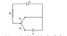
(1) The key S₁, is closed and S₂, is open. The value of current in the resistor after 5 seconds, is
(2) The final charge on the capacitor, when key S₁ is closed and S₂ is open, is: (A) 5μC (B) 5mC (C) 25 mC (D) 0.1C
(3) For sufficient time, if key S₁ is closed and S₂ is open, now key S₂ is closed and S₁ is open. What is the final charge on the capacitor? (A) Zero (B) 5mC (C) 2.5 mC (D) 5μC
(4) The dimensional formula for RC is:
[1 Mark](5) The key S₁, is closed and S₂, is open. The initial value of charging current in the resistor, is (A) 5mA (B) 0.5 mA (C) 2mA (D) 1mA
This matches with the concept in the case where charging current is maximum initially and decreases with time as capacitor charges.
A thin lens is a transparent optical medium bounded by two surfaces, at least one of which should be spherical. Applying the formula for image formation by a single spherical surface successively at the two surfaces of a lens, one can obtain the ‘lens maker formula’ and then the ‘lens formula’. A lens has two foci — called ‘first focal point’ and ‘second focal point’ of the lens, one on each side.
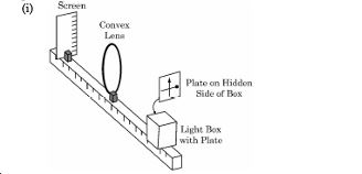
(1) Consider the arrangement shown in figure. A black vertical arrow and a horizontal thick line with a ball are painted on a glass plate. It serves as the object. When the plate is illuminated, its real image is formed on the screen. Which of the following statements is incorrect regarding lenses?
(2) Which of the following statements is incorrect ? (A) For a convex mirror magnification is always negative. (B) For all virtual images formed by a mirror magnification is positive. (C) For a concave lens magnification is always positive. (D) For real and inverted images, magnification is always negative.
(3) A convex lens of focal length ‘f’ is cut into two equal parts perpendicular to the principal axis. The focal length of each part will be: (A) f (B) 2f (C) f/2 (D) f/4
When a convex lens is cut into two equal parts perpendicular to the principal axis, each part behaves like a lens with half the aperture of the original lens but the same radii of curvature. According to the lens formula and lens maker’s formula given in the case, the focal length f depends on the curvature of surfaces and refractive index, which remain unchanged. However, halving the aperture decreases the lens power by half, effectively doubling the focal length to 2f for each half lens.
(4) If an object in case (i) above is 20 cm from the lens and the screen is 50 cm away from the object, the focal length of the lens used is (A) 10cm (B) 12cm (C) 16cm (D) 20cm
(5) The distance of an object from first focal point of a biconvex lens is X₁, and distance of the image from second focal point is X₂. The focal length of the lens is
Section B
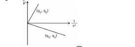
Figure shows variation of Coulomb force (F) acting between two point charges with 1/r² being the separation between the two charges (q₁ and q₂) and (q₂,q₃). If q₂ is positive and least in magnitude, then the magnitudes of q₁,q₂ and q₃ are such that:
Two wires P and Q are made of the same material. The wire Q has twice the diameter and half the length as that of wire P. If the resistance of wire P is R, the resistance of the wire Q will be:
A 1 cm segment of a wire lying along x-axis carries current of 0.5 A along +x direction. A magnetic field 𝐵⃗=(0.4 mT)𝑗̂+(0.6 mT)𝑘̂ is switched on in the region. The force acting on the segment is
A coil has 100 turns, each of area 0.05 m² and total resistance 1.5 Ω. It is inserted at an instant in a magnetic field of 90 mT, with its axis parallel to the field. The charge induced in the coil at that instant is:
You are required to design an air-filled solenoid of inductance 0.016 H having a length of 0.81 m and radius 0.02 m. The number of turns in the solenoid should be:
The inductance L of an air-filled solenoid is given by L = (μ₀ * N² * A) / l, where μ₀ = 4π × 10⁻⁷ H/m, N is number of turns, A is cross-sectional area, and l is length. Here, L = 0.016 H, l = 0.81 m, radius r = 0.02 m, so A = πr² = π (0.02)² = 1.256 × 10⁻³ m². Rearranging for N, we get N = sqrt((L * l) / (μ₀ * A)). Plugging the values, N ≈ sqrt((0.016 * 0.81) / (4π × 10⁻⁷ * 1.256 × 10⁻³)) ≈ 2866 turns. Hence, the correct option is 2866.
Assertion (A): It is difficult to move a magnet into a coil of large number of turns when the circuit of the coil is closed.
Reason (R): The direction of induced current in a coil with its circuit closed, due to motion of a magnet, is such that it opposes the cause.
A voltage v = v₀ sin ωt applied to a circuit drives a current i = i₀ sin (ωt+ φ) in the circuit. The average power consumed in the circuit over a cycle is
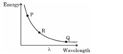
The given diagram exhibits the relationship between the wavelength of the electromagnetic waves and the energy of photon associated with them. The three points P, Q and R marked on the diagram may correspond respectively to :
A beaker is filled with water (refractive index 4/3) upto a height H. A coin is placed at its bottom. The depth of the coin, when viewed along the near normal direction, will be
The stopping potential V₀ measured in a photoelectric experiment for a metal surface is plotted against frequency v of the incident radiation. Let m be the slope of the straight line so obtained. Then the value of charge of an electron is given by (h is the Planck’s constant.)
Let λₑ, λₚ, λ_d be the wavelengths associated with an electron, a proton and a deuteron, all moving with the same speed. Then the correct relation between them is
Which of the following figures correctly represent the shape of curve of binding energy per nucleon as a function of mass number ?
-
(A)
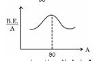
-
(B)
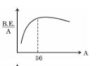
-
(C)
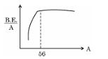
-
(D)
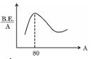
When a p-n junction diode is forward biased
Assertion (A) : The deflection in a galvanometer is directly proportional to the current passing through it.
Reason (R) =: The coil of a galvanometer is suspended in a uniform radial magnetic field.
Assertion (A) : We cannot form a p-n junction diode by taking a slab of a p-type semiconductor and physically joining it to another slab of a n-type semiconductor.
Reason (R) : In a p-type semiconductor ηₑ >> ηₕ, while in a n-type semiconductor ηₕ >>ηₑ.
Assertion (A) : The potential energy of an electron revolving in any stationary orbit in a hydrogen atom is positive.
Reason (R) : The total energy of a charged particle is always positive.
Section C
In a diffraction experiment, the slit is illuminated by light of wavelength 600 nm. The first minimum of the pattern falls at an angle of 30°. Calculate the width of the slit.
In a Young's double-slit experiment, two light waves, each of intensity I₀, interfere at a point, having a path difference λ/8 on the screen, Find the intensity at this point.
The resultant intensity I is given by I = 4 * I₀ * cos2(\u03B4/2) = 4 * I₀ * cos2(pi/8).
cos(pi/8) is approximately 0.9239, so I = 4 * I₀ * (0.9239)2 = 4 * I₀ * 0.8536 = 3.414 * I₀.
Therefore, the intensity at the point with path difference λ/8 is approximately 3.41 times I₀.
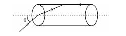
A transparent solid cylindrical rod (refractive index 2/√3) is kept in air. A ray of light incident on its face travels along the surface of the rod as shown in the figure. Calculate the critical angle θ .
Prove that, in the Bohr model of the hydrogen atom, the time period of revolution of an electron in nᵗʰ orbit is proportional to n³.
A p-type silicon semiconductor is made by doping an average of one dopant atom per 5 x 10⁷ silicon atoms. If the number density of silicon atoms in the specimen is 5 x 10²⁸ atoms m⁻³, find the number of holes created per cubic cm in the specimen due to doping. Also, give one example of such dopants.
(b) Number of holes created = Number of dopant atoms = 1 x 10²¹ holes/m3.
To convert into holes/cm3, 1 m3 = 106 cm3, so holes/cm3 = (1 x 10²¹) / (106) = 1 x 10¹⁵ holes/cm3.
(c) Example of dopants that create p-type silicon are trivalent elements like Boron (B) or Gallium (Ga).
Section D
Two batteries of emfs 3V & 6V and internal resistances 0.20Ω & 0.4Ω are connected in parallel. This combination is connected to a 4Ω resistor. Find :
i) the equivalent emf of the combination
ii) the equivalent internal resistance of the combination
iii) the current drawn from the combination
1. **Equations for equivalent emf and internal resistance**:
1/E_eq = 1/E_1 + 1/E_2
E_eq = (E_1*r_2 + E_2*r_1) / (r_1 + r_2)
2. For the given values,
E_1 = 3V, r_1 = 0.2Ω; E_2 = 6V, r_2 = 0.4Ω.
Finding E_eq:
E_eq = (3*0.4 + 6*0.2) / (0.2 + 0.4) = (1.2 + 1.2) / 0.6 = 4V.
Finding r_eq:
1/r_eq = 1/r_1 + 1/r_2 = 1/0.2 + 1/0.4 = 5 + 2.5 = 7.5
=> r_eq = 1/7.5 = 0.133Ω
To find current (I) through the 4Ω resistor, we use Ohm's Law:
I = E_eq / (R + r_eq) = 4V / (4Ω + 0.133Ω) = 4 / 4.133 ≈ 0.967A.
(i) A conductor of length l is connected across an ideal cell of emf E. Keeping the cell connected, the length of the conductor is increased to 2l by gradually stretching it. If R and R’ are initial and final values of resistance and V_d, and V_d' are initial and final values of drift velocity, find the relation between (i) R’ and R and (ii) V_d’ and V_d.
(ii) When electrons drift in a conductor from lower to higher potential, does it mean that all the ‘free electrons’ of the conductor are moving in the same direction ?
For drift velocity, with emf E constant, current I = E/R. Initial current I = E/R, final current I' = E/R' = E/(4R) = I/4. Drift velocity v_d = I / (nAe) where n is number density and e is charge. Since A changes to A/2, and I changes to I/4, v_d' = I' / (n A' e) = (I/4) / (n (A/2) e) = (I/4) * (2 / n A e) = v_d / 2. Thus, v_d' = v_d / 2.
(ii) No, not all free electrons move in the same direction. Electrons move randomly in all directions due to thermal motion, but when electric field is applied, electrons as a whole acquire a small average drift velocity opposite to the field. Hence, only the average motion is in one direction, while individual electrons move randomly.
Using Biot-Savart law, derive expression for the magnetic field (𝐁⃗) due to a circular current carrying loop at a point on its axis and hence at its centre.
Consider a circular loop of radius R carrying current I. Let P be a point on the axis of the loop at a distance x from its center O.
According to Biot-Savart law, the magnetic field element dB due to a current element Idl at point P is dB = (μ0 / 4π) * (I d𝐥 × r̂) / r2 where r is the distance from the element to P and r̂ is the unit vector along r.
Because of symmetry, the horizontal components cancel and only the components along the axis add up.
Using geometry, r = sqrt(R2 + x2) and the angle between d𝐥 and r is 90 degrees, so magnitude of dB = (μ0 / 4π) * (I dl sin 90deg) / r2 = (μ0 / 4π) * (I dl) / (R2 + x2).
The component along axis is dB cos θ where cos θ = x / sqrt(R2 + x2).
Integrating around the loop, total magnetic field B = (μ0 I / 4π) * (x / (R2 + x2)3/2) * ∮ dl = (μ0 I / 4π) * (x / (R2 + x2)3/2) * (2π R).
Simplifying, B = (μ0 I R2) / (2 (R2 + x2)3/2). The direction of B is along the axis.
Magnetic field at the centre of the loop (x = 0):
Putting x = 0 in above expression,
B = (μ0 I) / (2 R) along the axis (perpendicular to plane of loop).
This is the magnetic field at the centre of the circular loop carrying current I.
Summary:
Magnetic field on axis at distance x from centre: B = (μ0 I R2) / (2 (R2 + x2)3/2)
At centre (x=0): B = (μ0 I) / (2 R).
(a) Show that the energy required to build up the current I in a coil of inductance L is 1/2 LI².
(b) Considering the case of magnetic field produced by air-filled current carrying solenoid, show that the magnetic energy density of a magnetic field B is B² / 2μ0
(b) For an air-filled solenoid of length l, cross-sectional area A, and n turns per unit length carrying current I, the magnetic field produced is B = μ0 n I. Inductance L of the solenoid is L = μ0 n^2 l A. The total magnetic energy stored is U = (1/2) L I^2 = (1/2) μ0 n^2 l A I^2. Substituting I = B / (μ0 n), U = (1/2) μ0 n^2 l A (B / (μ0 n))^2 = (1/2) (B^2) l A / μ0. Magnetic energy density u is energy per unit volume V = l A, so u = U / V = (B^2) / (2 μ0). This shows that magnetic energy density of a magnetic field B is B squared divided by 2 μ0.
(a) A parallel plate capacitor is charged by an ac source. Show that the sum of conduction current (I_c) and the displacement current (I_d) has the same value at all points of the circuit.
(b) In case (a) above, is Kirchhoff’ first rule (junction rule) valid at each plate of the capacitor ? Explain.
(b) Kirchhoff's first rule states that sum of currents at a junction equals zero. At the plates of the capacitor, conduction current ends and displacement current starts. Since displacement current acts like a real current inside the capacitor, Kirchhoff's rule holds true at each plate. The sum of conduction and displacement currents is same on both sides of the capacitor plates, so the junction rule is valid.
Answer the following giving reason :
(a) All the photo electrons do not eject with the same kinetic energy when monochromatic light is incident on a metal surface.
(b) The saturation current in case (a) is different for different intensity.
(c) If one goes on increasing the wavelength of light incident on a metal
surface, keeping its intensity constant, emission of photo electrons
stop at a certain wavelength for this metal.
(a) Define ‘Mass defect’ and ‘Binding energy’ of a nucleus. Describe ‘Fission process’ on the basis of binding energy per nucleon.
(b) A deuteron contains a proton and a neutron and has a mass of 2.013553 u. Calculate the mass defect for it in u and its energy equivalence in MeV. (mₚ= 1.007277 u, mₙ= 1.008665 u, 1u = 931.5 MeV/ c²)
Binding energy is the energy required to break a nucleus into its constituent nucleons or equivalently, the energy released when a nucleus is formed from nucleons. It is due to mass defect according to Einstein’s equation E=mc2.
In the fission process, a heavy nucleus splits into two lighter nuclei releasing energy. This happens because the binding energy per nucleon of the resulting nuclei is higher than that of the original heavy nucleus, making the system more stable and energy is released.
(b) Mass of proton, mₑ = 1.007277 u, Mass of neutron, mₘ = 1.008665 u, Mass of deuteron, M = 2.013553 u
Sum of individual masses = 1.007277 + 1.008665 = 2.015942 u
Mass defect, Δm = (sum of individual masses) - (mass of nucleus) = 2.015942 - 2.013553 = 0.002389 u
Energy equivalent = Δm * 931.5 MeV = 0.002389 * 931.5 = 2.224 MeV
Hence, the mass defect is 0.002389 u and the binding energy is 2.224 MeV.
(a) Draw circuit arrangement for studying V-I characteristics of a p-n junction diode.
(b) Show the shape of the characteristics of a diode.
(c) Mention two information that you can get from these characteristics.
Section E
(i) Two-point charges 5 μC and -1 μC are placed at points (-3 cm,0, 0) and (3 cm, 0, 0) respectively. An external electric field 𝐸⃗=𝐴𝑟2 𝑟̂ where A = 3x 10⁵ Vm is switched on in the region. Calculate the change in electrostatic energy of the system due to the electric field. An external electric field
(ii) A system of two conductors is placed in air and they have net charge of +80 μC and —80μC which causes a potential difference of 16 V between them.
(1) Find the capacitance of the system.
(2) If the air between the capacitor is replaced by a dielectric medium of dielectric constant 3, what will be the potential difference between the two conductors?
(3) If the charges on two conductors are changed to +160 μC and —160 μC, will the capacitance of the system change? Give reason for your answer.
(ii) (1) Capacitance of the system: Charge Q = 80 μC = 80 * 10-6 C, Potential difference V = 16 V. Capacitance C = Q / V = (80 * 10-6) / 16 = 5 * 10-6 F = 5 μF.
(2) New potential difference when dielectric is inserted: With dielectric constant k = 3, capacitance increases to C' = k * C = 3 * 5 μF = 15 μF. Since charge Q remains same, new potential difference V' = Q / C' = (80 * 10-6) / (15 * 10-6) = 5.33 V.
(3) Effect of changing charges on capacitance: Capacitance depends only on geometry and dielectric, not on charge or voltage. So changing charges to +160 μC and —160 μC will not change capacitance; it remains 5 μF or 15 μF if dielectric is present. Reason: Capacitance C = Q / V, so for increased charge, voltage also changes proportionally, keeping capacitance constant.
(i) Consider three metal spherical shells A, B and C, each of radius R. Each shell is having a concentric metal ball of radius R/10. The spherical shells A, B and C are given charges +6q, —4q, and 14q respectively. Their inner metal balls are also given charges —2q, +8q and —10q respectively. Compare the magnitude of the electric fields due to shells A, B and C at a distance 3R from their centres.
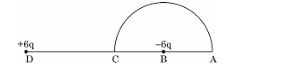
(ii) A charge —6 μC is placed at the centre B of a semicircle of radius 5 cm, as shown in the figure. An equal and opposite charge is placed at point D at a distance of 10 cm from B. A charge +5 μC is moved from point ‘C’ to point ‘A’ along the circumference. Calculate the work done on the charge.
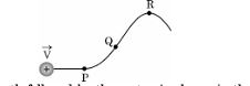
(i) A proton moving with velocity 𝐕⃗ in a non-uniform magnetic field traces a path as shown in the figure.
The path followed by the proton is always in the plane of the paper. What is the direction of the magnetic field in the region near points P, Q and R? What can you say about relative magnitude of magnetic fields at these points?
(ii) A current carrying circular loop of area A produces a magnetic field B at its centre. Show that the magnetic moment of the loop is 2BA/μ0 √(A/π).
(ii) The magnetic moment (μ) of a current-carrying loop is defined as the product of current (I) and area (A), that is μ = I A. The magnetic field at the center of a circular loop carrying current I is given by B = μ0 I / (2 R), where R is the radius of the loop and μ0 is permeability of free space. Now, area A = π R2, so radius R = sqrt(A / π). From the magnetic field expression, I = 2 B R / μ0. Substituting in μ = I A, we get μ = (2 B R / μ0) * A = 2 B A R / μ0 = 2 B A / μ0 * sqrt(A / π). Hence, magnetic moment of the loop is μ = 2 B A / μ0 * sqrt(A / π).
(i) Derive an expression for the torque acting on a rectangular current loop suspended in a uniform magnetic field.
(ii) A charged particle is moving in a circular path with velocity 𝐕⃗ in a uniform magnetic field 𝐁⃗. It is made to pass through a sheet of lead and as a consequence, it looses one half of its kinetic energy without change in its direction. How will (1) the radius of its path (2) its time period of revolution change ?
Consider a rectangular loop of length l and breadth b carrying a current I placed in a uniform magnetic field B. If the plane of the loop makes an angle with the magnetic field, the forces on opposite sides of the loop create a couple, producing a torque on the loop.
The magnetic moment of the loop is .
The torque acting on the loop is given by .
The magnitude of torque is .
Thus, torque where A is the area of the loop.
(ii) Effect on radius and time period of charged particle after losing half kinetic energy:
Let initial velocity of particle be v, charge q, mass m, magnetic field B.
1. Radius of path .
2. Time period , independent of velocity.
After passing through lead sheet, velocity reduces because kinetic energy halves:
Initial kinetic energy , final kinetic energy so new velocity .
1. New radius , radius decreases by factor .
2. Time period depends only on m, q, B and remains unchanged.
Summary:
Radius decreases by but time period remains the same after kinetic energy halves without change in direction.
(i) (1) What are coherent sources ? Why are they necessary for observing a sustained interference pattern?
(2) Lights from two independent sources are not coherent. Explain.
(ii) Two slits 0.1 mm apart are arranged 1.20 m from a screen. Light of wavelength 600 nm from a distant source is incident on the slits.
(1) How far apart will adjacent bright interference fringes be on the screen ?
(2) Find the angular width (in degree) of the first bright fringe.
(i) Define a wavefront. An incident plane wave falls on a convex lens and gets refracted through it. Draw a diagram to show the incident and refracted wavefront.
(ii) A beam of light coming from a distant source is refracted by a spherical glass ball (refractive index 1.5) of radius 15 cm. Draw the ray diagram and obtain the position of the final image formed.
For the spherical glass ball, considering a distant light source, the incoming rays can be approximated as parallel. The glass ball refracts these rays according to the lens-maker's formula: 1/f = (n-1)(1/R1 - 1/R2). For a radius of 15 cm and a refractive index of 1.5, the effective focal length f can be calculated. A ray diagram will show these incoming parallel rays converging, forming a real image on the opposite side of the ball. The exact image position can be determined from the geometry of the setup. Overall, the incident rays converge at a point determined by the properties of the lens.
Paper Details
CBSE Board Exam 2025
Class
Class 12 PCM
Subject
Physics
Year
2025
Set
Set 1
Other Years — Physics