SOLUTIONS
2024 BOARD EXAM
CBSE Class 12 PCM Physics Board Paper 2024 — Set 4 Solutions
2024
Physics
Class 12 PCM
CBSE EXAMINATION PAPER-2024
PHYSICS
(Solved)
General Instructions :
Read the following instructions carefully and follow them :
- This question paper contains 38 questions. All questions are compulsory.
- This question paper is divided into 5 sections.
- Section A – questions number 1 to 2 are case based questions
- Section B – questions number 3 to 18 are multiple choice questions
- Section C – questions number 19 to 24 are very short answer
- Section D – questions number 25 to 32 are short answer
- Section E – questions number 33 to 38 are long answer
- There is no overall choice given in the question paper. However, an internal choice has been provided in few questions.
- Use of calculator is NOT allowed.
Section A
(1) When Ge is doped with pentavalent impurity, the energy required to free the weakly bound electron from the dopant is about (A) 0.001 eV (B) 0.01 eV (C) 0.72eV (D) 1.1eV
(2) At a given temperature, the number of intrinsic charge carriers in a semiconductor is 2.0 x 10¹⁰cm⁻³. It is doped with pentavalent impurity atoms. As a result, the number of holes in it becomes 8 x 10³ cm⁻³. The number of electrons in the semiconductor is 2×10²⁴ m⁻³ 4×10²³ m⁻³ 1×10²² m⁻³ 5×10²² m⁻³
(3) (a) During the formation of a p-n junction — (A) electrons diffuse from p-region into n-region and holes diffuse from n-region into p-region. (B) both electrons and holes diffuse from n-region into p-region. (C) electrons diffuse from n-region into p-region and holes diffuse from p-region into n-region. (D) both electrons and holes diffuse from p-region into n-region.
(4) An ac voltage V = 0.5 sin (100 π t) volt is applied, in turn, across a half-wave rectifier and a full-wave rectifier. The frequency of the output voltage across them respectively will be (A) 25 Hz, 50 Hz (B) 25 Hz, 100 Hz (C) 50 Hz, 50 Hz (D) 50 Hz, 100 Hz
(5) (b) Initially during the formation of a p-n junction — (A) diffusion current is large and drift current is small. (B) diffusion current is small and drift current is large. (C) both the diffusion and the drift currents are large. (D) both the diffusion and the drift currents are small.
Initially, when the p-n junction is formed, due to the concentration gradient, holes diffuse from p-side to n-side and electrons from n-side to p-side, creating a large diffusion current. The drift current is small at this stage as the electric field has not yet fully developed to oppose diffusion. This is explained in the case where diffusion and drift processes occur during pn junction formation.
(1) The radii of curvature of two surfaces of a convex lens are R and 2R. If the focal length of this lens is 4/3R, the refractive index of the material of the lens is: 5/3 4/3 3/2 7/5
(2) A thin converging lens of focal length 20 cm and a thin diverging lens of focal length 15 cm are placed coaxially in contact. The power of the combination is -5/6D -5/3D 4/3D 3/2D
This shows that the power of the combination is negative, meaning the combination acts as a diverging lens.
(3) The focal length of an equiconvex lens (A) increases when the lens is dipped in water. (B) increases when the wavelength of incident light decreases. (C) increases with decrease in radius of curvature of its surface. (D) decreases when the lens is cut into two identical parts along its principal axis.
(4) (a) A thin convex lens L of focal length 10 cm and a concave mirror M of focal length 15 cm are placed coaxially 40 cm apart as shown in figure. A beam of light coming parallel to the principal axis is incident on the lens. The final image will be formed at a distance of (A) 10cm, left of lens (B) 10cm, right of lens (C) 20cm, left of lens (D) 20cm, right of lens
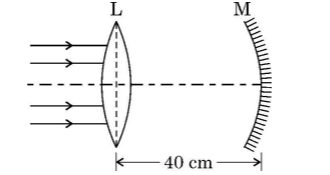 [1 Mark]
(5) A beam of light coming parallel to the principal axis of a convex lens L₁, of focal length 16 cm is incident on it. Another convex lens L₂, of focal length 12 cm is placed coaxially at a distance 40 cm from L₁,. The nature and distance of the final image from L₂, will be (A) real, 24cm (B) virtual, 12 cm (C) real, 32 cm (D) virtual, 18 cm
Section B
Two charges + q each are kept ‘2a’ distance apart. A third charge -2q is placed midway between them. The potential energy of the system is-
Two identical small conducting balls B₁, and B₂, are given -7 pC and + 4 pC charges respectively. They are brought in contact with a third identical ball B₃, and then separated. If the final charge on each ball is -2 pC, the initial charge on B₃, was
The quantum nature of light explains the observations on photoelectric effect as-
The correct answer is (A) there is a minimum frequency of incident radiation below which no electrons are emitted. This is because the photoelectric effect demonstrates that only light above a certain frequency can cause the emission of electrons from a metal, which is a key aspect of its quantum nature. If the frequency is too low, no electrons are emitted regardless of the intensity of the light.
A straight wire is kept horizontally along east-west direction. If a steady current flows in wire from east to west, the magnetic field at a point above the wire will point towards.
According to the right-hand rule for current-carrying conductors, if you point your thumb in the direction of the current (east to west), your fingers will curl in the direction of the magnetic field. Therefore, above the wire, the magnetic field will point towards the north.
The magnetic susceptibility for a diamagnetic material is
The correct option is 'small and negative.' Diamagnetic materials have a very small and negative susceptibility, which means they are repelled by magnetic fields. This is due to the absence of unpaired electrons in their atomic structure, resulting in no net magnetic moment.
A galvanometer of resistance 100 Ω is converted into an ammeter of range (0 — 1 A) using a resistance of 0.1 Ω. The ammeter will show full scale deflection for a current of about
The correct answer is 1 mA. In this scenario, the galvanometer has a resistance of 100 ohms, and when it is converted into an ammeter, the external shunt resistance used is 0.1 ohms. To find the full scale deflection current (Ifsd), we can use the formula: Ifsd = (Vg / Rg) + I, where Vg is the voltage across the galvanometer at full deflection, Rg is the galvanometer resistance, and I is the shunt current. Given that it is designed for a maximum current of 1 A and considering the ratio of resistances, the full scale deflection current will be approximately 1 mA.
A circular loop A of radius R carries a current I. Another circular loop B of radius r (=R/20) is placed concentrically in the plane of A. The magnetic flux linked with loop B is proportional to
Figure shows the variation of inductive reactance X_L of two ideal
inductors of inductance L₁, and L₂, with angular frequency ω. The value of L₁/L₂ is
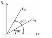
The inductive reactance X_L of an inductor is given by X_L = ωL, where ω is angular frequency and L is the inductance. The variation of X_L with ω will be a straight line passing through the origin with slope equal to L. From the graph, the slope of the X_L vs ω line for the inductor with inductance L₁ is 3 times the slope for L₂, indicating that L₁/L₂ = 3.
The phase difference between electric field 𝐄⃗ and magnetic field 𝐁⃗ in an
electromagnetic wave propagating along z-axis is
In an electromagnetic wave, the electric field (E) and the magnetic field (B) oscillate perpendicular to each other and to the direction of wave propagation. The phase difference between E and B in an electromagnetic wave is always 0 (they reach their maximum and minimum values simultaneously), thus the correct answer is '0'.
A coil of N turns is placed in a magnetic field 𝐁⃗ such that 𝐁⃗ is perpendicular to the plane of the coil. 𝐁⃗ changes with time as
B = B₀ cos (2πt/T) where T is time period. The magnitude of emf induced in the coil will be maximum at....
Here, n = 1, 2, 3, 4, ...
In Balmer series of hydrogen atom, as the wavelength of spectral lines decreases, they appear
As the wavelength decreases, the energy of the emitted photons increases, which leads to the spectral lines getting closer together in the Balmer series. This is because the energy levels become closer together at higher frequencies.
Assertion (A) : The temperature coefficient of resistance is positive for metals and negative for p-type semiconductors.
Reason (R) : The charge carriers in metals are negatively charged,whereas the majority charge carriers in p-type semiconductors are positively charged.
Assertion (A) : When electrons drift in a conductor, it does not mean that all free electrons in the conductor are moving in the same direction.
Reason (R) : The drift velocity is superposed over large random velocities of electrons.
Assertion (A) : Electrons are ejected from the surface of zinc when it is irradiated by yellow light.
Reason (R) : Energy associated with a photon of yellow light is more than the work function of zinc.
Assertion (A) : In interference and diffraction of light, light energy reduces in one region producing a dark fringe. It increases in another region and produces a bright fringe.
Reason (R) : This happens because energy is not conserved in the phenomena of interference and diffraction.
The assertion (A) is true because in interference and diffraction, light energy is redistributed such that regions of dark and bright fringes occur due to reduction and increase of light intensity respectively. However, the reason (R) is false because energy is conserved in these phenomena. The apparent decrease in one region is balanced by increase in another, so there is no loss or gain of total light energy, consistent with the principle of conservation of energy.
The radius (rₙ) of nᵗʰ orbit in Bohr model of hydrogen atom varies with n as
Section C
Draw the circuit diagram of a p-n junction diode in
(i) forward biasing and (ii) reverse biasing. Also draw its I-V characteristics in the two cases.
A proton and α-particle are accelerated through different potentials V₁ and V₂ respectively so that they have the same de Broglie wavelengths. Find V₁ / V₂.
A ray of light is incident normally on one face of an equilateral glass prism of refractive index μ. When the prism is completely immersed in a transparent medium, it is observed that the emergent ray just grazes the adjacent face. Find the refractive index of the medium.
Step 1: Since the ray is incident normally on one face, there is no refraction at the first surface.
Step 2: The ray travels inside the prism and reaches the second face at an angle of incidence equal to the prism angle, 60 deg.
Step 3: The emergent ray just grazes the adjacent face, implying the angle of refraction in the medium is 90 deg (critical condition).
Step 4: Using Snell's law at the second face: μ / μ_medium = 1 / sin 60 deg => μ_medium = μ * sin 60 deg = μ * (sqrt(3)/2).
Answer: The refractive index of the medium is μ_medium = μ * (sqrt(3)/2).
Two electric heaters have power ratings P₁ and P₂ at voltage V. They are connected in series to a dc source of voltage V. Find the power consumed by the combination. Will they consume the same power if connected in parallel across the same source?
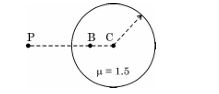
An air bubble is trapped at point B (CB = 20 cm) in a glass sphere of radius 40 cm and refractive index 1.5 as shown in figure. Find the nature and position of the image of the bubble as seen by an observer at point P.
In normal adjustment, for a refracting telescope, the distance between objective and eye piece lens is 1.00 m. If the magnifying power of the telescope is 19, find the focal length of the objective and the eyepiece lens.
Magnifying power, M = 19
In normal adjustment, the length of the telescope L = fo + fe, where fo is focal length of objective and fe is focal length of eyepiece.
Also, magnifying power M = fo / fe
From magnification, fo = 19 * fe
Substitute in L: 100 = 19 fe + fe = 20 fe
=> fe = 100 / 20 = 5 cm
Then, fo = 19 * 5 = 95 cm
Therefore, focal length of objective lens is 95 cm and focal length of eyepiece lens is 5 cm.
Section D
(a) Differentiate between nuclear fission and fusion.
(b) The fission properties of ₉₄Pu²³⁹ are very similar to those of ₉₂ U²³⁵. How much energy (in MeV), is released if all the atoms in 1 g of pure ₉₄Pu²³⁹ undergo fission? The average energy released per fission is 180 MeV.
1. Nuclear fission is the process of splitting a heavy nucleus into two lighter nuclei, while nuclear fusion is the process of combining two light nuclei to form a heavier nucleus.
2. Fission releases energy by breaking down heavy atoms like U-235 or Pu-239, fusion releases energy by fusing light atoms like hydrogen isotopes.
3. Fission produces radioactive waste, fusion produces less or no radioactive waste.
4. Fission is used in nuclear reactors and atomic bombs, fusion is the process that powers the sun and is being researched for fusion reactors.
(b) Given: Mass of Pu-239 = 1 g = 0.001 kg
Atomic mass of Pu-239 = 239 g/mol
Energy per fission = 180 MeV
Number of moles in 1 g Pu = 1 / 239 = 0.004184 mol
Number of atoms in 1 g Pu = 0.004184 * 6.022 * 1023 = 2.52 * 1021 atoms
Total energy released = Number of atoms * Energy per fission
= 2.52 * 1021 * 180 MeV
= 4.536 * 1023 MeV
Therefore, the energy released if all atoms in 1 g of Pu-239 undergo fission is approximately 4.54 * 1023 MeV.
Draw the graph showing variation of scattered particles detected (N) with the scattering angle (θ) in Geiger-Marsden experiment. Write two conclusions that you can draw from this graph. Obtain the expression for the distance of closest approach in this experiment.
(b) Two conclusions from the graph are: 1. Most alpha particles pass through the foil with little or no deflection, showing that atoms are mostly empty space.
2. A small fraction of alpha particles are scattered at large angles, indicating a small, dense, positively charged nucleus at the center.
(c) Expression for distance of closest approach (d): When an alpha particle of charge +2e and kinetic energy K comes close to a nucleus of charge +Ze, it stops at distance d due to electrostatic repulsion, so kinetic energy equals electric potential energy.
Therefore, K = (1 / (4 * pi * epsilon0)) * (2e * Ze) / d
=> d = (1 / (4 * pi * epsilon0)) * (2Ze2) / K
This distance d is called distance of closest approach.
The electric field in a region is given by 𝐄⃗ =(10x+4)𝑖̂
where x is in m and E is in N/C. Calculate the amount of work done in taking a unit charge from
i) (5m, 0) to (10 m, 0)
ii) (5m, 0) tom, 10 m)
Work done (W) in moving a charge q in an electric field is W = q * (V_final - V_initial). For a unit charge, q = 1 C, so W = V_final - V_initial.
Since E = -dV/dx, we have dV = -E dx => V = -∫E dx + constant.
Step 1: Find potential difference between points:
V(x) = -∫(10x + 4) dx = - (5x2 + 4x) + C
(i) Work done in moving from x = 5 m to x = 10 m:
W = V(10) - V(5) = [ - (5*102 + 4*10) ] - [ - (5*52 + 4*5) ] = [ - (500 + 40) ] - [ - (125 + 20) ] = (-540) - (-145) = -540 + 145 = -395 J
(ii) For the second part, the question as given appears incomplete or incorrectly typed as "tom, 10 m". Assuming it means from (5 m, 0) to (10 m, 10 m). Since electric field is only along x and does not depend on y, moving along y does no work.
Work done only depends on x-displacement:
Work = same as part (i) = -395 J.
Note: Negative work done indicates that the electric force does work on the charge, or the charge loses potential energy moving from 5 m to 10 m.
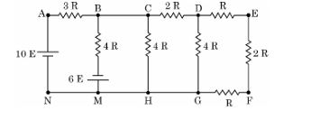
Find the current in branch BM in the network shown.
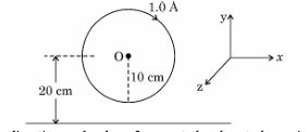
A circular loop of radius 10 cm carrying current of 1.0 A lies in x-y plane. A long straight wire lies in the same plane parallel to x-axis at a distance of 20 cm as shown in figure. Find the direction and value of current that has to be maintained in the wire so that the net magnetic field at O is zero. 3
Name the electromagnetic waves with their wavelength range which are
used for
i) FM radio broadcast
ii) detection of fracture in bones
iii) treatment of muscular strain
(a) (i) Define mutual inductance. Write its SI unit.
(ii) Derive an expression for the mutual inductance of a system of two long coaxial solenoids of same length l, having turns N₁, and N₂, and of radii r₁, and r₂> r₁.
(ii) Derivation of mutual inductance for two coaxial solenoids: Consider two long coaxial solenoids of same length l. The inner solenoid S1 has N1 turns and radius r1, and the outer solenoid S2 has N2 turns and radius r2 > r1. Let n1 = N1/l and n2 = N2/l be the turns per unit length.
When current I1 flows through the inner solenoid, magnetic field inside it is B = μ0 n1 I1 (where μ0 is permeability of free space). This field passes through the outer solenoid as well.
The magnetic flux through one turn of outer solenoid due to inner solenoid is Φ = B * Area = μ0 n1 I1 * π r12. Total flux linked with outer solenoid is N2 * Φ = N2 μ0 n1 π r12 I1.
Mutual inductance M is defined as total flux linked per unit current, so M = N2 μ0 n1 π r12. Substituting n1 = N1/l, M = (μ0 π r12 N1 N2)/l.
Thus, M = μ0 π r12 N1 N2 / l.
(b) What are ferromagnetic materials? Explain ferromagnetism with the help of suitable diagrams, using the concept of magnetic domain.
Section E
(a) (i) Draw a ray diagram for the formation of the image of an object by a convex mirror. Hence, obtain the mirror equation.
(ii) Why are multi-component lenses used for both the objective and the eyepiece in optical instruments ?
(iii) The magnification of a small object produced by a compound microscope is 200. The focal length of the eyepiece is 2 cm and the final image is formed at infinity. Find the magnification produced by the objective.
Mirror formula derivation: Using sign conventions, for a mirror, 1/f = 1/v + 1/u, where f is focal length, v is image distance, u is object distance. For convex mirror, focal length f is positive; image distance v is negative (since image is virtual and behind mirror). Hence the mirror formula holds as 1/f = 1/v + 1/u.
(a)(ii) Use of multi-component lenses in optical instruments: Multi-component lenses (compound lenses) are used for the objective and eyepiece to reduce chromatic and spherical aberrations. Different lens materials and shapes help correct these aberrations, improving image quality and clarity by minimizing color fringing and distortion.
(a)(iii) Finding magnification of the objective: Given total magnification M = 200, focal length of eyepiece f_e = 2 cm, and final image at infinity. Magnification by eyepiece m_e = D / f_e where D is least distance of distinct vision (usually 25 cm). So m_e = 25/2 = 12.5.
Then, magnification by objective m_o = M / m_e = 200 / 12.5 = 16.
Thus, magnification produced by the objective is 16.
(i)Using Gauss’s law, show that the electric field 𝐄⃗ at a point due to a uniformly charged infinite plane sheet is given by 𝐸⃗=𝜎/2𝜖0𝑛̂ where symbols have their usual meanings.
(ii)Electric field E in a region is given by
𝐄⃗ = (5x² + 2)𝑖̂
where E is in N/C and x is in meters.
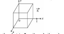
A cube of side 10 cm is placed in the region as shown in figure.
Calculate (1) the electric flux through the cube, and (2) the net charge enclosed by the cube.
meters.
Consider an infinite plane sheet with uniform charge density sigma (σ) C/m2. To find the electric field E at a point near the sheet, choose a Gaussian surface in the form of a cylinder with its flat faces parallel to the plane, one face above and one face below the sheet.
The electric field is perpendicular to the surface and has the same magnitude on both faces. Let the area of each face be A.
Flux through the curved surface is zero because the electric field is parallel to the curved surface.
Total electric flux, Φ = E * A + E * A = 2EA
By Gauss’s law, Φ = q_enclosed / epsilon_0 = sigma * A / epsilon_0
Equate the two expressions:
2EA = sigma * A / epsilon_0
=> E = sigma / (2 epsilon_0)
Direction of E is normal to the sheet, denoted by the unit vector n^
Hence, E = (sigma / 2 epsilon_0) n^
(ii) Given electric field E = (5x^2 + 2) i^ N/C, cube side a = 10 cm = 0.1 m:
(1) Electric flux through the cube:
Electric flux Φ = ∮ E · dA
The electric field has x-component only; flux passes through faces perpendicular to x-axis
Two faces at x = 0 and x = 0.1 m, each of area A = 0.1 * 0.1 = 0.01 m2
Flux through face at x=0 (where E = 5*0^2 + 2 = 2 N/C) outward area vector is -i^, so flux is E · (-i^) * A = -2 * 0.01 = -0.02 Nm2/C
Flux through face at x=0.1 (E = 5*(0.1)^2 + 2 = 5*0.01 + 2 = 2.05 N/C), area vector is +i^, flux = 2.05 * 0.01 = 0.0205 Nm2/C
Flux through other faces is zero because E is perpendicular to their area vectors
Total flux Φ = 0.0205 - 0.02 = 0.0005 Nm2/C
(2) Net charge enclosed by the cube using Gauss’s law:
q_enclosed = epsilon_0 * Φ = 8.854 * 10-12 * 0.0005 = 4.427 * 10-15 C
Final answers:
E due to infinite sheet = sigma / (2 epsilon_0) n^
Electric flux through cube = 0.0005 Nm2/C
Net charge enclosed = 4.427 * 10-15 C
(i) Mention the factors on which the resonant frequency of a series LCR circuit depends. Plot a graph showing variation of impedance of a series LCR circuit with the frequency of the
applied a.c. source.
(ii) With the help of a suitable diagram, explain the working of a step-up transformer.
(iii) Write two causes of energy loss in a real transformer.
(ii) A step-up transformer consists of two coils: primary and secondary, wound on an iron core. When AC flows through the primary coil, it produces a changing magnetic flux in the core. This changing flux induces an emf in the secondary coil according to Faraday's law of electromagnetic induction. Since the number of turns in the secondary coil is greater than in the primary coil, the induced emf in the secondary coil is higher. Thus, the transformer steps up the voltage from primary to secondary.
(iii) Two causes of energy loss in a real transformer are:
1. Eddy current loss: Circulating currents induced in the iron core produce heat.
2. Hysteresis loss: Energy is lost due to the lagging of magnetic domains in the core material when the magnetic field changes repeatedly.
(i) Differentiate between a wavefront and a ray.
(ii) State Huygen’s principle and verify laws of reflection using suitable diagram.
(iii) In Young’s double slit experiment, the slits S₁ and S₂, are 3 mm apart and the screen is placed 1.0 m away from the slits. It is observed that the fourth bright fringe is at a distance of 5 mm from the second dark fringe. Find the wavelength of light used.
A wavefront is an imaginary surface representing points of a wave vibrating in phase, i.e., points having the same phase of oscillation. It can be spherical, plane, or cylindrical depending on the source.
A ray is a line drawn perpendicular to the wavefront indicating the direction of energy propagation of the wave.
(ii) Huygen's Principle:
Every point on a given wavefront acts as a source of secondary spherical wavelets, and the new wavefront at any later time is the envelope of these wavelets.
Verification of laws of reflection using Huygen's principle:
Consider a plane wavefront AB incident on a reflecting surface at an angle of incidence i.
According to Huygen's principle, each point on AB acts as a source of secondary wavelets.
After reflection, the wavelets form a new wavefront A'B'. The angle between the incident wavefront and the surface is 90deg - i.
The reflected wavefront makes the same angle of 90deg - r with the surface.
Therefore, the angle of incidence i equals the angle of reflection r (i = r), verifying the law of reflection.
(iii) Calculation of wavelength in Young's double slit experiment:
Given:
Distance between slits, d = 3 mm = 3 * 10-3 m
Distance between screen and slits, D = 1.0 m
Distance between 4th bright fringe and 2nd dark fringe, x = 5 mm = 5 * 10-3 m
In Young's experiment,
Position of nth bright fringe from central maximum, y_b = n * (λ * D / d)
Position of mth dark fringe from central maximum, y_d = (m - 1/2) * (λ * D / d)
Here, 4th bright fringe and 2nd dark fringe correspond to n=4 and m=2 respectively.
Distance between them, Δy = y_b - y_d
= 4 * (λ * D / d) - (3/2) * (λ * D / d) = (4 - 1.5) * (λ * D / d) = 2.5 * (λ * D / d)
Given Δy = 5 * 10-3 m, so
5 * 10-3 = 2.5 * (λ * 1 / 3 * 10-3)
=> λ = (5 * 10-3) * (3 * 10-3) / 2.5 = 6 * 10-6 m = 600 nm
Therefore, the wavelength of light used is 600 nm.
(i) A dielectric slab of dielectric constant ‘K' and thickness ‘t’ is inserted between plates of a parallel plate capacitor of plate separation d and plate area A. Obtain an expression for its
capacitance.
(ii) Two capacitors of different capacitances are connected first (1) in series and then (2) in parallel across a de source of 100 V. If the total energy stored in the combination in the two cases are 40 mJ
and 250 mJ respectively, find the capacitance of the capacitors.
Consider a capacitor with plate area A and plate separation d. A dielectric slab of dielectric constant K and thickness t is inserted between the plates. The remaining space (d - t) is air (dielectric constant 1).
Since the dielectric slab and air separate the plates in series, the system can be treated as two capacitors in series:
C1 = capacitance of air portion = epsilon_0 * A / (d - t)
C2 = capacitance of dielectric slab = K * epsilon_0 * A / t
The total capacitance C is given by 1/C = 1/C1 + 1/C2, so
1/C = (d - t) / (epsilon_0 * A) + t / (K * epsilon_0 * A) = [ (d - t) + t / K ] / (epsilon_0 * A)
Therefore,
C = epsilon_0 * A / [ (d - t) + t / K ]
This is the expression for capacitance when a dielectric slab of thickness t and dielectric constant K is inserted.
(ii) Finding capacitances of two capacitors from energy stored:
Let the two capacitors have capacitances C1 and C2.
Given: Voltage V = 100 V
Energy stored in series combination, U_series = 40 mJ = 40 * 10-3 J
Energy stored in parallel combination, U_parallel = 250 mJ = 250 * 10-3 J
For series:
Equivalent capacitance, C_series = (C1 * C2) / (C1 + C2)
Energy stored, U_series = 1/2 * C_series * V2
=> 40 * 10-3 = 1/2 * (C1 * C2) / (C1 + C2) * (100)2
=> (C1 * C2) / (C1 + C2) = 8 * 10-3 F ...(1)
For parallel:
Equivalent capacitance, C_parallel = C1 + C2
Energy stored, U_parallel = 1/2 * C_parallel * V2
=> 250 * 10-3 = 1/2 * (C1 + C2) * (100)2
=> C1 + C2 = 5 * 10-2 F ...(2)
From equation (2), C1 + C2 = 0.05 F
From equation (1), (C1 * C2) / (0.05) = 0.008
=> C1 * C2 = 0.0004 F2
Now we solve quadratic equation:
x2 - (C1 + C2) x + C1 * C2 = 0
x2 - 0.05 x + 0.0004 = 0
Solving for x:
x = [0.05 +- sqrt(0.052 - 4 * 1 * 0.0004)] / 2
= [0.05 +- sqrt(0.0025 - 0.0016)] / 2
= [0.05 +- sqrt(0.0009)] / 2
= [0.05 +- 0.03] / 2
So,
C1 = (0.05 + 0.03)/2 = 0.04 F
C2 = (0.05 - 0.03)/2 = 0.01 F
Hence, the two capacitances are 0.04 F and 0.01 F.
(i) With the help of a diagram, briefly explain the construction and working of ac generator.
(ii) An electron is revolving around a proton in an orbit of radius r with a speed v. Obtain expression for magnetic moment associated with the electron.
Working of AC Generator: When the coil rotates with angular velocity in the magnetic field, magnetic flux through the coil changes continuously. According to Faraday's law, this changing magnetic flux induces an emf (electromotive force) in the coil. As the coil rotates, the emf changes polarity after every half rotation, producing an alternating current (AC). The slip rings ensure smooth transfer of this alternating current to the external circuit via the brushes without tangling the wires.
(ii) When an electron revolves around a proton in a circular orbit of radius r with speed v, it constitutes a current loop.
Current (I): The electron completes one revolution in time T = 2*pi*r / v, so current I = charge / time = e / T = e * v / (2 * pi * r).
Magnetic moment (μ): The magnetic moment of a current loop is given by μ = I * A, where A is the area of the loop = pi * r2.
Therefore, μ = (e * v / (2 * pi * r)) * (pi * r2) = (e * v * r) / 2.
Thus, the magnetic moment associated with the electron is μ = (e * v * r) / 2, directed perpendicular to the plane of the orbit according to the right-hand rule.
Paper Details
CBSE Board Exam 2024
Class
Class 12 PCM
Subject
Physics
Year
2024
Set
Set 4
Other Years — Physics