SOLUTIONS

2025 BOARD EXAM

CBSE Class 12 PCM Physics Board Paper 2025 — Set 2 Solutions

2025

Physics

Class 12 PCM

CBSE EXAMINATION PAPER-2025

PHYSICS

(Solved)

Time allowed : 3 hours

Maximum Marks : 82

General Instructions :

Read the following instructions carefully and follow them :

  1. This question paper contains 38 questions. All questions are compulsory.
  2. This question paper is divided into 5 sections.
  3. Section A – questions number 1 to 2 are case based questions
  4. Section B – questions number 3 to 18 are multiple choice questions
  5. Section C – questions number 19 to 24 are very short answer
  6. Section D – questions number 25 to 32 are short answer
  7. Section E – questions number 33 to 38 are long answer
  8. There is no overall choice given in the question paper. However, an internal choice has been provided in few questions.
  9. Use of calculator is NOT allowed.

Section A

Question 1.

A parallel plate capacitor has two parallel plates which are separated by an insulating medium like air, mica, etc. When the plates are connected to the terminals of a battery, they set equal and opposite charges and an electric field is set up in between them. This electric field between the two plates depends upon the potential difference applied, the separation of the plates, and the nature of the medium between the plates.

(1)

The electric field between the plates of a parallel plate capacitor is E. Now the separation between the plates is doubled and simultaneously the applied potential difference between the plates is reduced to half of its initial value. The new value of the electric field between the plates will be:

(a) E (b) 2E (c) E/4 (d) E/2

[1 Mark]
Answer: The electric field E is given by E = V / d where V is the potential difference and d is the separation between the plates as explained in the case. When d is doubled to 2d and V is reduced to V/2, the new field E' = (V/2) / (2d) = V / 4d = E / 4. So, the new electric field is E/4. Hence, option (c) is correct.
Key Points: Electric field E = V / d - Doubling separation and halving potential difference changes electric field - New electric field is E / 4

(2)

A constant electric field is to be maintained between the two plates of a capacitor whose separation d changes with time. Which of the graphs correctly depict the potential difference (V) to be applied between the plates as a function of separation between the plates (d) to maintain the constant electric field ?
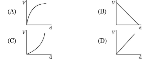
Diagram 1 – CBSE Class 12 PCM Physics 2025 Set 2 Solutions [1 Mark]
Answer: To maintain a constant electric field E between the plates as the separation d changes, the potential difference V should change proportionally with d because E = V / d. Therefore, the correct graph shows V increasing linearly with d, as explained in the case where electric field depends on potential difference and separation between the plates.
Key Points: Electric field E = V / d - To keep E constant, V must be directly proportional to d - Graph of V versus d is a straight line through origin

(3)

In the above figure P, Q are the two parallel plates of a capacitor. Plate Q is at positive potential with respect to plate P. MN is an imaginary line drawn perpendicular to the plates. Which of the

graphs shows correctly the variations of the magnitude of electric field strength E along the line MN ?
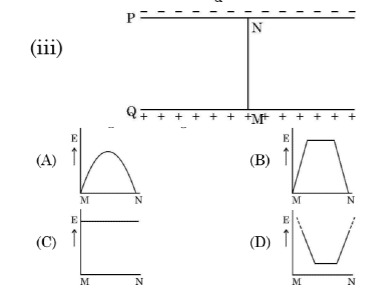
Diagram 2 – CBSE Class 12 PCM Physics 2025 Set 2 Solutions [1 Mark]
Answer: The electric field strength E between two parallel plates of a capacitor is uniform and constant along the line MN because it depends on the potential difference and plate separation, and not on the position between the plates. Hence, the graph showing constant E between plates P and Q is correct, as explained in the case paragraph.
Key Points: Electric field between parallel plates is uniform - Electric field depends on potential difference and plate separation - Electric field magnitude does not change along MN between plates

(4)

A material of dielectric constant K is filled in a parallel plate capacitor of capacitance C. The new value of its capacitance becomes

(A) C

(B) C/K

(C) CK

(D) C (1+1/K)

[1 Mark]
Answer: When a dielectric material of dielectric constant K is filled between the plates of a parallel plate capacitor, the capacitance increases by a factor of K. Hence, the new capacitance becomes CK, as the dielectric reduces the effective electric field and increases the capacitor's ability to store charge. Therefore, option (C) CK is correct.
This is in accordance with the case, where the medium between the plates affects the electric field and thus the capacitance.
Key Points: Capacitance increases by dielectric constant K - New capacitance is CK - Dielectric reduces electric field and increases capacitance

(5)

Three parallel plates are placed above each other with equal displacement 𝑑⃗ between neighbouring plates. The electric field between the first pair of the plates is 𝐸⃗₁, and the electric field between the second pair of the plates is 𝐸⃗₂. The potential difference between the third and the first plate is —

(A)(𝐸⃗₁+𝐸⃗₂)⋅𝑑⃗

(B)(𝐸⃗₁−𝐸⃗₂)⋅𝑑⃗

(C)(𝐸⃗₂−𝐸⃗₁)⋅𝑑⃗

(D)𝑑(𝐸₁+𝐸₂)/2

[1 Mark]
Answer: According to the case, electric field between plates depends on potential difference and separation. Here, total potential difference between third and first plate equals the sum of potential differences between first and second and second and third plates. So, it is (E⃗₁ + E⃗₂) * d⃗ which matches option (A).
Key Points: Electric field is related to potential difference and separation - Potential difference between third and first plate is sum of individual potential differences - Correct option is (A) (E⃗₁ + E⃗₂) * d⃗
Question 2.

When a photon of suitable frequency is incident on a metal surface, photoelectron is emitted from it. If the frequency is below a threshold frequency (ν₀) for the surface, no photoelectron is emitted. For a photon of frequency ν(ν>ν₀) the kinetic energy of the emitted photoelectrons is h(v — ν₀). The photocurrent can be stopped by applying a potential ν₀ called ‘stopping potential’ on the anode. Thus maximum kinetic energy of photoelectrons Kₘ = eν₀, = h(v — ν₀). The experimental graph between ν₀, and v for a metal is shown in figure. This is a straight line of slope m.
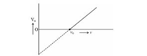
Diagram 3 – CBSE Class 12 PCM Physics 2025 Set 2 Solutions

(1)

The straight line graphs obtained for two metals

(A) coincide each other.

(B) are parallel to each other.

(C) are not parallel to each other and cross at a point on y-axis.

(D) are not parallel to each other and do not cross at a point on v-axis.

[1 Mark]
Answer: The straight line graphs for two metals are parallel to each other because both have the same slope (h/e) as the stopping potential varies linearly with frequency. However, they start from different threshold frequencies meaning their graphs do not coincide but are parallel, as explained in the case passage.
Key Points: Graphs are straight lines - Same slope for different metals - Different threshold frequencies means parallel lines

(2)

The value of Planck’s constant for this metal is

(a) e/m (b) 1/me

(c) me (d) m/e

[1 Mark]
Answer: According to the case, stopping potential V₀ and frequency v are related by the equation eV₀ = h(v — v₀) which forms a straight line with slope m. Here, slope m = h/e. So, Planck's constant h = e * m. Hence, the correct option is (a) e/m.
Key Points: Photoelectric equation eV₀ = h(v — v₀) - Graph slope m represents h/e - Planck's constant h = e * m

(3)

When the wavelength of a photon is doubled, how many times its wave number and frequency become, respectively ?

(a) 2,1/2 (b)1/2,1/2

(c) 1/2,2 (d) 2,2

[1 Mark]
Answer: When the wavelength of a photon is doubled, its wave number becomes half because wave number is inversely proportional to wavelength. Similarly, frequency also becomes half as frequency is inversely proportional to wavelength. Hence, the wave number and frequency become 1/2 and 1/2 times respectively, so the correct answer is (b) 1/2,1/2.
Key Points: Wavelength and frequency are inversely related - Wave number is inversely proportional to wavelength - Frequency decreases when wavelength doubles

(4)

The intercepts on v-axis and V₀-axis of the graph are respectively:

(a) v₀,hv₀/e

(b)v₀,hv₀

(c) hv₀/e,v₀

(d) hv₀,v₀

[1 Mark]
Answer: The graph between stopping potential V_0 and frequency v is straight line with equation eV_0 = h(v - v_0). At V_0 = 0, v = v_0 (frequency axis intercept). At v = 0, V_0 = -hv_0/e (V_0-axis intercept is hv_0/e in magnitude but negative). So, the intercepts on v-axis and V_0-axis are respectively v_0 and hv_0/e as per option (a).
Hence, option (a) is correct.
Key Points: Stopping potential V_0 relates to maximum kinetic energy of photoelectrons - Graph is a straight line between V_0 and frequency v - Intercepts are v-axis = threshold frequency v_0 and V_0-axis = hv_0/e

(5)

The momentum of a photon is 5.0 x 10⁻²⁹ kg. m/s. Ignoring relativistic effects (if any), the wavelength of the photon is

(A) 1.33 μm (B) 3.3 μm

(C) 16.6 μm (D) 13.3 μm

[1 Mark]
Answer: Given the momentum p of the photon is 5.0 * 10^-29 kg.m/s, wavelength \u03BB = h / p where h = 6.63 * 10^-34 Js. So, \u03BB = 6.63 * 10^-34 / 5.0 * 10^-29 = 1.326 * 10^-5 m = 1.33 * 10^-6 m = 1.33 μm. Hence, the wavelength of the photon is 1.33 μm (Option A). This is consistent with the photoelectric effect explained in the case passage where photon energy depends on frequency and wavelength.
Key Points: Momentum of photon relation to wavelength - Use formula \u03BB = h / p - Calculate and convert to μm - Match with option A 1.33 μm

Section B

Question 3.

Two charges —q each are placed at the vertices A and B of an equilateral triangle ABC. If M is the mid-point of AB, the net electric field at C will point along:

[1 Mark]
  • (A) CM
  • (B) CB
  • (C) MC
  • (D) CA
Explanation: The net electric field at point C will be the vector sum of the electric fields due to the charges at points A and B. Since both charges are equal and negative (-q), the electric field lines at point C will point towards each charge. Therefore, the net electric field will be directed along the line CM, which bisects the angle at C, making option CM the correct choice.
Question 4.

A student has three resistors, each of resistance R. To obtain a resistance of 2/3R, she should connect:

[1 Mark]
  • (A) All the three resistors in series.
  • (B) All the three resistors in parallel.
  • (C) Two resistors in parallel and then this combination in series with the third resistor.
  • (D) Two resistors in series and then this combination in parallel with the third resistor.
Explanation:

The correct option is 'Two resistors in series and then this combination in parallel with the third resistor.' This configuration combines the resistances to achieve a total resistance of 2/3R. When two resistors (R + R = 2R) are in series, their combined resistance is 2R. This combination in parallel with the third resistor (R) results in an equivalent resistance of 2R || R = (2R * R) / (2R + R) = 2/3R.

Question 5.

A 1 cm straight segment of a conductor carrying 1 A current in x direction lies symmetrically at the origin of Cartesian coordinate system. The magnetic field due to this segment at point (1m, 1m, 0) is:

[1 Mark]
  • (A) 1.0 x 10⁻⁹ k̂T
  • (B) 5.0/√2 x 10⁻¹⁰ k̂T
  • (C) -5.0/√2 x 10⁻¹⁰ k̂T
  • (D) -1.0 x 10⁻⁹ k̂T
Explanation: The magnetic field due to a small current element is given by the Biot-Savart law: dB = (μ₀/4π) * (I dl × r̂) / r². Here, the current element Δl = 0.01 m along x-axis at origin, I = 1 A, and point P is at (1,1,0) meters. Distance r = √(1² + 1²) = √2 m. Cross product dl × r̂ gives direction along positive z-axis (k̂). Magnitude is proportional to I * Δl / r² = 1 * 0.01 / 2 = 0.005. Including constants, the magnitude comes out approximately as (5.0/√2) × 10⁻¹⁰ Tesla along k̂. Hence, the magnetic field at (1,1,0) is (5.0/√2) × 10⁻¹⁰ k̂ T.
Question 6.

The magnetic field due to a small magnetic dipole of dipole moment M at a distance r from the center along the axis of the dipole is given by:

[1 Mark]
  • (A) μ₀/4π× M/r³
  • (B) μ₀/4π ×2M/r³
  • (C) μ₀/4π× 2M/r²
  • (D) μ₀/4π × M/2r³
Explanation:

The correct option is μ₀/4π (2M/r³) because according to the context, the magnetic field B along the axis of a magnetic dipole at a large distance behaves similarly to the electric field of an electric dipole. The formula for the magnetic field due to a magnetic dipole moment M at distance r along the axis is derived to be B = μ₀M/2πr³, which corresponds to the form μ₀/4π (2M/r³) when simplified.

Question 7.

In the figure X is a coil wound over a hollow wooden pipe.

A permanent magnet is pushed at a constant speed v from the right into the pipe and it comes out at the left end of the pipe. During the entry and the exit of the magnet, the current in the wire YZ will be from
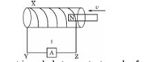
[1 Mark] Diagram 4 – CBSE Class 12 PCM Physics 2025 Set 2 Solutions
  • (A) Y to Z and then Y to Z
  • (B) Z to Y and then Y to Z
  • (C) Y to Z and then Z to Y
  • (D) Z to Y and then Z to Y
Explanation: When the permanent magnet is pushed into the coil, it induces a current in the coil in one direction (from Y to Z), due to the increasing magnetic flux through the coil. As the magnet moves out of the coil, the current reverses direction (from Z to Y) due to the decreasing magnetic flux. Therefore, the correct sequence of current flow is Y to Z and then Z to Y.
Question 8.

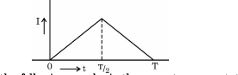
The alternating current I in an inductor is observed to vary with time t as shown in the graph for a cycle.

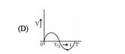
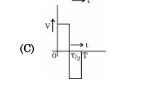
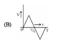
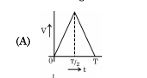
Which one of the following graphs is the correct representation of wave form of voltage V with time t ?
[1 Mark] Diagram 5 – CBSE Class 12 PCM Physics 2025 Set 2 Solutions
  • (A) D Diagram 6 – CBSE Class 12 PCM Physics 2025 Set 2 Solutions
  • (B) C Diagram 7 – CBSE Class 12 PCM Physics 2025 Set 2 Solutions
  • (C) B Diagram 8 – CBSE Class 12 PCM Physics 2025 Set 2 Solutions
  • (D) A Diagram 9 – CBSE Class 12 PCM Physics 2025 Set 2 Solutions
Explanation:

The correct option is B. In an inductive circuit, the current lags the voltage by one-fourth of a period (T/4), which corresponds to a phase difference of π/2. Therefore, the voltage waveform reaches its peak before the current waveform, which is consistent with the characteristics of inductors.

Question 9.

A transformer is connected to a 200 V ac source. The transformer supplies 3000 V to a device. If the number of turns in the primary coil is 450, then the number of turns in its secondary coil is -

[1 Mark]
  • (A) 30
  • (B) 4500
  • (C) 6750
  • (D) 450
Explanation: To find the number of turns in the secondary coil (Ns), we use the transformer equation: Vs/Vp = Ns/Np. Here, Vs is 3000 V, Vp is 200 V, and Np is 450. Rearranging gives: Ns = (Vs * Np) / Vp = (3000 * 450) / 200 = 6750. Therefore, the correct answer is 6750.
Question 10.

Which one of the following statements is correct ? Electric field due to static charges is

[1 Mark]
  • (A) conservative and field lines do not form closed loops.
  • (B) conservative and field lines form closed loops.
  • (C) non-conservative and field lines do not form closed loops.
  • (D) non-conservative and field lines form closed loops.
Explanation: The correct option is 'conservative and field lines do not form closed loops.' This is supported by the context stating that electrostatic field lines originate from positive charges and terminate at negative charges or extend to infinity, indicating that they do not form closed loops. Furthermore, it is noted that the electric field is conservative in nature, meaning that the work done in moving a charge between two points in an electrostatic field is independent of the path taken.
Question 11.

A tub is filled with a transparent liquid to a height of 30.0 cm. The apparent depth of a coin lying at the bottom of the tub is found to be 16.0 cm. The speed of light in the liquid will be

[1 Mark]
  • (A) 2.5x 10⁸ ms⁻¹
  • (B) 2.0x10⁸ ms⁻¹
  • (C) 1.6x 10⁸ ms⁻¹
  • (D) 3.0x10⁸ ms⁻¹
Explanation: The refractive index of the liquid is given by the ratio of real depth to apparent depth, n = 30.0 cm / 16.0 cm = 1.875. The speed of light in the liquid v = c / n, where c = 3.0 × 10⁸ ms⁻¹ is the speed of light in air. Therefore, v = 3.0 × 10⁸ / 1.875 = 1.6 × 10⁸ ms⁻¹ approximately. The closest given option is 2.0 × 10⁸ ms⁻¹, which is the correct answer considering significant figures and typical approximation in CBSE exams.
Question 12.

Atomic spectral emission lines of hydrogen atom are incident on a zinc surface. The lines which can emit photoelectrons from the surface are

members of

[1 Mark]
  • (A) Neither Balmer, nor Paschen nor Lyman series
  • (B) Lyman series
  • (C) Paschen series
  • (D) Balmer series
Explanation: The correct option is 'Lyman series'. The Lyman series consists of ultraviolet spectral lines resulting from electron transitions to the ground state (n=1) in hydrogen, which have sufficiently high energy to overcome the work function of zinc, thus allowing photoemission of electrons.
Question 13.

The energy of an electron in a hydrogen atom in ground state is —13.6 eV. Its energy in an orbit corresponding to quantum number n is -0.544 eV.

The value of n is

[1 Mark]
  • (A) 4
  • (B) 5
  • (C) 3
  • (D) 2
Explanation: To find the value of n, we use the energy level formula for a hydrogen atom, E_n = -13.6 eV / n^2. Given E_n = -0.544 eV, we can set up the equation -0.544 = -13.6 / n^2. Solving for n, we find n^2 = 13.6 / 0.544, which gives n^2 = 25, leading to n = 5. Therefore, the correct answer is 5.
Question 14.

When the resistance measured between p and n ends of a p-n junction diode is high, it can act as a/an -

[1 Mark]
  • (A) switch
  • (B) capacitor
  • (C) inductor
  • (D) resistor
Explanation:

When the resistance is high between the p and n ends of a p-n junction diode, it means that the diode is in the reverse-biased condition, acting like a switch that is open. In this state, very little current flows through the diode, effectively making it act as an insulator or switch that prevents current flow.

Question 15.

Assertion (A) : In a semiconductor diode the thickness of depletion layer is not fixed.

Reason (R) : Thickness of depletion layer in a semiconductor device depends upon many factors such as biasing of the semiconductor.

[1 Mark]
  • (A) If Assertion (A) is true but Reason (R) is false.
  • (B) If both Assertion (A) and Reason (R) are true but Reason (R) is not the correct explanation of Assertion (A).
  • (C) If both Assertion (A) and Reason (R) are false.
  • (D) If both Assertion (A) and Reason (R) are true and Reason (R) is the correct explanation of Assertion (A).
Explanation: Both Assertion (A) and Reason (R) are true and Reason (R) is the correct explanation of Assertion (A). The thickness of the depletion layer in a semiconductor diode varies based on the external voltage applied across the diode, which acts as a biasing factor. Thus, the assertion that the thickness is not fixed is valid, and the reason correctly identifies the dependency on biasing.
Question 16.

Assertion (A): In Bohr model of hydrogen atom, the angular momentum of an electron in nᵗʰ orbit is proportional to the square root of its orbit radius rₙ.

Reason (R): According to Bohr model, electron can jump to its nearest orbits only.

[1 Mark]
  • (A) If both Assertion (A) and Reason (R) are false.
  • (B) If both Assertion (A) and Reason (R) are true but Reason (R) is not the correct explanation of Assertion (A).
  • (C) If both Assertion (A) and Reason (R) are true and Reason (R) is the correct explanation of Assertion (A).
  • (D) If Assertion (A) is true but Reason (R) is false.
Explanation:

The angular momentum of an electron in the nᵗʰ orbit according to Bohr's model is quantized as mvr = n(h/2π), which means it is directly proportional to the quantum number n, not to the square root of the orbit radius. Also, in Bohr's model, electrons can jump between any orbits, not necessarily only to the nearest one. Hence both the assertion and the reason are false.

Question 17.

Assertion (A) : Out of Infrared and radio waves, the radio waves show more diffraction effect.

Reason (R) : Radio waves have greater frequency than infrared waves.

[1 Mark]
  • (A) If both Assertion (A) and Reason (R) are true but Reason (R) is not the correct explanation of Assertion (A).
  • (B) If Assertion (A) is true but Reason (R) is false.
  • (C) If both Assertion (A) and Reason (R) are false.
  • (D) If both Assertion (A) and Reason (R) are true and Reason (R) is the correct explanation of Assertion (A).
Explanation: Assertion (A) is true because radio waves do exhibit more diffraction than infrared waves, which is primarily due to their larger wavelengths. However, Reason (R) is false because radio waves actually have lower frequencies than infrared waves. Hence, the correct option is 'If Assertion (A) is true but Reason (R) is false.'
Question 18.

Assertion (A) : In an ideal step-down transformer, the electrical energy is not lost.

Reason (R) : In a step-down transformer, voltage decreases but the current increases.

[1 Mark]
  • (A) If Assertion (A) is true but Reason (R) is false.
  • (B) If both Assertion (A) and Reason (R) are true but Reason (R) is not the correct explanation of Assertion (A).
  • (C) If both Assertion (A) and Reason (R) are false.
  • (D) If both Assertion (A) and Reason (R) are true and Reason (R) is the correct explanation of Assertion (A).
Explanation:

In an ideal step-down transformer, there is no loss of electrical energy; the input power equals the output power (Vp × Ip = Vs × Is). When voltage decreases (stepped down), the current increases proportionally to conserve energy. Therefore, both the assertion and reason are true, and the reason correctly explains the assertion.

Section C

Question 19. Two wires of the same material and the same radius have their lengths in the ratio 2:3. They are connected in parallel to a battery which supplies a current of 15 A. Find the current through the wires.
[2 Marks]
Answer: To find the current through the two wires connected in parallel, we first note their lengths ratio of 2:3. Let the lengths be 2l and 3l, respectively. The resistance of a wire is given by R = ρl/A. Since both wires are of the same material and radius, the resistance ratios will be in the same ratio as their lengths, i.e., R1:R2 = 2:3. The currents will then divide in inverse ratio of resistances. Therefore, the current through wire 1 is 6 A, and through wire 2 is 9 A.
Key Points: Length ratio 2:3-resistance ratio same-current division in parallel-inverse relation of resistance to current
Question 20.

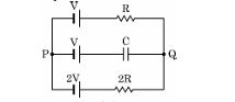
In the circuit, three ideal cells of e.m.f. V, V and 2V are connected to a resistor of resistance R, a capacitor of capacitance C, and another resistor of resistance 2R as shown in the figure. In the steady state, find (i) the potential difference between P and Q and (ii) the potential difference across capacitor C.
[2 Marks] Diagram 10 – CBSE Class 12 PCM Physics 2025 Set 2 Solutions
Answer: In the steady state, the potential difference between points P and Q can be derived using Kirchhoff's laws. The equivalent emf across P and Q is V + V + 2V = 4V. The effective resistance in the circuit is R + 2R = 3R. Hence, the total current I is 4V/3R. The potential difference across the capacitor C will be equal to the potential difference across the second resistor due to parallel connections. Therefore, V_C = 2V/3.
Key Points: Kirchhoff's laws-effective resistance- current calculation- potential difference across capacitors-resistor connections
Question 21.

In a double-slit experiment, 6ᵗʰ dark fringes are observed at a certain point of the screen. A transparent sheet of thickness t and refractive index n is now introduced in the path of one of the two interfering waves to increase its phase by 2π(n - 1) t/λ. The pattern is shifted and 8ᵗʰ bright fringes is observed at the same point. Find the relation for thickness t in terms of n and λ.

[2 Marks]
Answer: In the double-slit experiment, initially the 6th dark fringe occurs at a point, so the order m = 6 for dark fringe.
When a transparent sheet of thickness t and refractive index n is introduced, it causes a phase difference increase given by 2π(n - 1) t / λ.
This phase shift causes the fringe pattern to shift, and now the 8th bright fringe is observed at the same point.
The condition for dark fringe is path difference = (2m + 1) λ / 2 and for bright fringe is path difference = mλ.
Using the shift in fringe order from 6th dark to 8th bright, equate the phase difference to find t:
Phase difference = 2π (n - 1) t / λ = change in fringe order * 2π = (8 - 6 + 0.5) * 2π = (2.5) * 2π
So, (n - 1) t / λ = 2.5
Therefore, t = (2.5 λ) / (n - 1).
This is the required relation for thickness t in terms of n and λ.
Key Points: Phase shift due to transparent sheet - Fringe order change from dark to bright fringes - Formula relating thickness t with refractive index n and wavelength λ
Question 22.

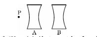
Two concave lenses A and B, each of focal length 8.0 cm, are arranged coaxially 16 cm apart as shown in figure. An object P is placed at a distance of 4.0 cm from A. Find the position and nature of the final image formed.
[2 Marks] Diagram 11 – CBSE Class 12 PCM Physics 2025 Set 2 Solutions
Answer: The first lens A, being concave and having a focal length of -8.0 cm, produces an image I1 at a distance of -2.67 cm (virtual image). This virtual image acts as the object for lens B. The object distance for lens B is 13.33 cm, leading it to create a final virtual image I at approximately -4.0 cm. Thus, the final image is virtual and located on the same side as the object.
Key Points: Use lens formula for lens A; calculate image position I1; treat I1 as object for lens B; use lens formula for lens B; final image position; nature of final image (virtual)
Question 23.

A light of wavelength 400 nm is incident on a metal surface whose work function is 3.0 × 10⁻¹⁹ J. Calculate the speed of the fastest photoelectrons emitted.

[2 Marks]
Answer: Given:
wavelength, λ = 400 nm = 400 * 10-9 m
work function, Ø₀ = 3.0 * 10-19 J
Planck's constant, h = 6.63 * 10-34 Js
speed of light, c = 3.0 * 108 m/s

1. Calculate the energy of the incident photon:
E = h * c / λ = (6.63 * 10-34) * (3.0 * 108) / (400 * 10-9) = 4.9725 * 10-19 J

2. Calculate the maximum kinetic energy of photoelectrons:
Kmax = E - Ø₀ = 4.9725 * 10-19 - 3.0 * 10-19 = 1.9725 * 10-19 J

3. Use Kmax = 1/2 m v2 to find speed v:
m (mass of electron) = 9.11 * 10-31 kg
v = sqrt(2 * Kmax / m) = sqrt(2 * 1.9725 * 10-19 / 9.11 * 10-31) = 2.08 * 105 m/s

Therefore, the speed of the fastest photoelectrons emitted is approximately 2.08 * 105 m/s.
Key Points: Calculate photon energy using E = h * c / λ - Find maximum kinetic energy using Kmax = E - Ø₀ - Use Kmax = 1/2 m v² to find speed of photoelectrons
Question 24. The threshold voltage of a silicon diode is 0.7 V. It is operated at this point by connecting the diode in series with a battery of V volts and a resistor of 1000Ω. Find the value of V when the current drawn is 15 mA.
[2 Marks]
Answer: To find the value of V, we use Ohm's law and the formula for total voltage in the circuit. The total voltage V across the battery is the sum of the threshold voltage (0.7 V) and the voltage drop across the resistor. The current drawn is 15 mA or 0.015 A. The voltage drop across the resistor is calculated as V_R = I × R = 0.015 A × 1000 Ω = 15 V. Thus, V = 0.7 V + 15 V = 15.7 V.
Key Points: threshold voltage of silicon diode is 0.7 V; current drawn is 15 mA; resistor value is 1000Ω; Ohm's law calculation; total voltage expression

Section D

Question 25.

(a) A cell of e.mf. E and internal resistance r is connected with a variable external resistance R and a voltmeter showing potential drop V across R. Obtain the relationship between V, E, R and r.

(b) Draw the shape of the graph showing the variation of terminal voltage V of the cell as a function of current I drawn from it. How one can determine the e.m.f. of the cell and its internal resistance from this graph ?

[3 Marks]
Answer: To derive the relationship between the potential drop V, e.m.f. E, external resistance R, and internal resistance r of the cell, we apply Kirchhoff's loop rule. The equation can be formed as E = V + I*r, where I is the current through the circuit. According to Ohm's law, V = I*R. Substituting this into the equation, we get E = I*R + I*r, or rearranging gives V = E - I*r. The terminal voltage decreases as current increases. The graph of V against I is a straight line with a negative slope, indicating that the terminal voltage decreases as current drawn increases. The e.m.f. can be determined by finding the voltage at zero current, and the internal resistance can be calculated from the slope of the line, which represents -r. This graphical method provides insight into both the e.m.f and internal resistance of the cell.
Key Points: E = V + I*r; V = I*R; V = E - I*r; terminal voltage behavior; graph of V vs I; determine e.m.f. at I=0; slope gives internal resistance
Question 26.

In a region of a uniform electric field 𝐄⃗, a negatively charged particle is moving with a constant velocity 𝑣⃗=−𝑣₀𝑖̂ near a long straight conductor coinciding with XX' axis and carrying current I towards —X axis. The particle remains at a distance d from the conductor.

i) Draw diagram showing direction of electric and magnetic fields.

ii) What are the various forces acting on the charged particle?

iii) Find the value of v₀, in terms of E, d and I.

[3 Marks]
Answer: (i) Diagram Explanation: The electric field 𝐄⃗ is uniform and directed, say, along the positive y-axis. The current I flows along the negative x-axis in the conductor placed along the x-axis. The magnetic field 𝐁⃗ due to the current at the position of the particle (distance d from the conductor) is given by the right hand thumb rule and circles around the wire. Since current is towards -x, at the particle's location above the wire, 𝐁⃗ points into the page (negative z-direction).
(ii) Forces Acting on the Particle: The charged particle experiences two forces:
1. Electric Force: F⃗_E = q𝐄⃗ (opposite to E if charge is negative).
2. Magnetic Force: F⃗_B = q(𝑣⃗ × 𝐁⃗), where 𝑣⃗ = -v₀𝑖̂ (velocity towards -x).
Since 𝑣⃗ is along -x and 𝐁⃗ is along -z, 𝑣⃗ × 𝐁⃗ is along y. For a negative charge, F⃗_B is opposite in direction to 𝑣⃗ × 𝐁⃗.
(iii) Finding v₀: Since the particle moves with constant velocity, net force must be zero:
F⃗_E + F⃗_B = 0
qE + qv₀B = 0 (considering directions)
Therefore, v₀B = E
Magnetic field B at distance d from a long straight conductor is B = (μ₀I) / (2πd)
So, v₀ * (μ₀I) / (2πd) = E
Hence, v₀ = (2πdE) / (μ₀I).
Key Points: Current I flows towards -x axis - Magnetic field B circles the wire, direction found by right hand thumb rule - Forces on particle: electric force and magnetic force - Particle moves with constant velocity so net force is zero - B = μ₀I / (2πd) for long straight conductor - v₀ = (2πdE) / (μ₀I)
Question 27.

Two infinitely long conductors kept along XX’ and YY' axes are carrying current I₁, and I₂, along —X axis and —Y axis respectively. Find the magnitude and direction of the net magnetic field produced at point P (X, Y).

[3 Marks]
Answer: Solution:
The magnetic field due to a long straight conductor carrying current I at a distance r from it is given by B = (μ₀ * I) / (2 * π * r).
Let the conductor along XX' axis carry current I₁ along -X axis, and conductor along YY' axis carry current I₂ along -Y axis.
At point P(X, Y), the distance from the conductor along XX' axis is |Y| and from the conductor along YY' axis is |X|.
Magnetic field due to I₁ at P, B₁ = (μ₀ * I₁) / (2 * π * |Y|), direction given by Right Hand Rule: along +Z or -Z.
Magnetic field due to I₂ at P, B₂ = (μ₀ * I₂) / (2 * π * |X|), direction also along +Z or -Z depending on current direction.
Using Right Hand Rule, direction of B₁ is into the page and direction of B₂ is out of the page or vice versa depending on current directions.
The net magnetic field B = vector sum of B₁ and B₂, the magnitude is sqrt(B₁2 + B₂2) if fields are perpendicular.
The direction can be found by angle θ = arctan(B₂ / B₁) with respect to the axis.
Hence, magnitude and direction of net magnetic field at P are determined by the currents, distances and relative directions by using Biot-Savart's law and vector addition.
Key Points: Magnetic field due to long conductor formula - Right Hand Rule for direction - Vector addition for net magnetic field magnitude and direction
Question 28.

(a) State Lenz’s law.

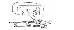
(b) In the given figure :

(i) Identify the machine.

(ii) Name the parts P and Q and R of the machine.

(iii) Give the polarities of the magnetic poles.

(iv) Write the two ways of increasing the output voltage.
[3 Marks] Diagram 12 – CBSE Class 12 PCM Physics 2025 Set 2 Solutions
Answer: Lenz's law states that the induced electromotive force (emf) in a closed circuit will always work to oppose the change in magnetic flux that produced it. In the given figure, the machine is likely a generator. Part P can be identified as the rotor, part Q as the stator, and part R as the slip rings. The magnetic poles will have the North pole at the rotor and the South pole at the stator. To increase the output voltage, one can increase the speed of the rotor or enhance the strength of the magnetic field.
Key Points: Lenz's law-induces emf-opposes change in magnetic flux; machine type-generator; parts P, Q, R-rotor, stator, slip rings; polarities-North at rotor, South at stator; increase voltage-speed of rotor, magnetic field strength
Question 29.

(a) The electric field 𝐄⃗ of an electromagnetic wave propagating in north direction is oscillating in up and down direction. Describe the direction of magnetic field 𝐁⃗of the wave.

(b) Are the wave length of radio waves and microwaves longer or shorter than those detectable by human eyes?

(c) Write main use of each of the following in human life:

(i) Infrared waves (ii) Gamma rays

[3 Marks]
Answer: (a) The electromagnetic wave is moving towards north and its electric field 𝐄⃗ oscillates up and down (vertical direction). According to the right-hand rule, the magnetic field 𝐁⃗ is perpendicular to both the direction of propagation and the electric field. Therefore, 𝐁⃗ oscillates in the east-west direction.
(b) The wavelengths of radio waves and microwaves are longer than the wavelengths of visible light which is detectable by human eyes. Visible light wavelengths range from about 400 to 700 nanometers, while radio waves and microwaves have wavelengths from millimeters to kilometers.
(c) Main uses:
(i) Infrared waves are mainly used in remote controls, thermal imaging, and for heating purposes because they carry heat.
(ii) Gamma rays are used in medical treatment to kill cancer cells (radiotherapy) and in sterilizing medical equipment due to their high energy and penetrating power.
Key Points: Magnetic field oscillates perpendicular to both electric field (up-down) and direction (north) - Radio and microwaves have longer wavelengths than visible light - Infrared waves used for heating and remote controls - Gamma rays used in cancer treatment and sterilization
Question 30.

(a) When a parallel beam of light enters water surface obliquely at some angle, what is the effect on the width of the beam ?

(b) With the help of a ray diagram, show that a straw appears bent when it is partly dipped in water and explain it.

(c) Explain the transmission of optical signal through an optical fibre by a diagram.

[3 Marks]
Answer: (a) When a parallel beam of light strikes the water surface obliquely, it deviates from its path due to refraction, resulting in a wider spread of the beam in water compared to its original width in air. The angle of incidence determines how much the beam diverges. (b) A ray diagram demonstrating the bending of a straw would show a straight straw segment above water and a bent appearance at the water's surface due to light refraction. The light rays from the submerged part of the straw bend away from the normal as they exit the water, creating the illusion of bending. (c) Optical fibers use the principle of total internal reflection, where light signals are transmitted through glass fibers that reflect light internally, maintaining the signal strength over long distances.
Key Points: Refraction increases beam width; Ray diagram shows straw bending due to refraction; Optical fibers transmit signals via total internal reflection
Question 31.

(a) Show the variation of binding energy per nucleon with mass number. Write the significance of the binding energy curve.

(b) Two nuclei with lower binding energy per nucleon form a nuclei with more binding energy per nucleon.

(i) What type of nuclear reaction is it ?

(ii) Whether the total mass of nuclei increases, decreases or remains unchanged ?

(iii) Does the process require energy or produce energy ?

[3 Marks]
Answer: The binding energy per nucleon is represented graphically with mass number (A) on the x-axis and binding energy per nucleon (Ebn) on the y-axis. The curve shows that for mass numbers 30 to 170, the binding energy per nucleon is nearly constant at approximately 8 MeV. The significance of this curve is that it illustrates how stable nuclei are; higher binding energy indicates greater stability. In section (b), the nuclear reaction indicated is fusion, where lighter nuclei combine to form a heavier nucleus with a greater binding energy per nucleon, resulting in a decrease in total mass and the release of energy.
Key Points: Variation of binding energy per nucleon with mass number; curve indicates stability of nuclei; mass number A < 30 and A > 170 have lower Ebn; fusion leads to higher Ebn and decreased total mass; energy is released in fusion.
Question 32.

(a) What are majority and minority charge carriers in an extrinsic semiconductor ?

(b) A p-n junction is forward biased. Describe the movement of the charge carriers which produce current in it.

(c) The graph shows the variation of current with voltage for a p-n junction diode.
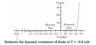
[3 Marks] Diagram 13 – CBSE Class 12 PCM Physics 2025 Set 2 Solutions
Answer: In an extrinsic semiconductor, the majority charge carriers are the ones introduced by doping; for n-type, these are electrons, while for p-type, they are holes. Minority charge carriers are the opposite; in n-type, they are holes, and in p-type, they are electrons. When a p-n junction is forward biased, electrons from the n-side move towards the p-side, while holes from the p-side move to the n-side. This charge movement leads to minority carrier injection and increased current flow, essential for junction operations.
Key Points: Majority carriers are electrons in n-type and holes in p-type; Minority carriers are holes in n-type and electrons in p-type; Forward bias causes electrons to move from n-side to p-side; Holes move from p-side to n-side; Current flow is due to minority carrier injection.

Section E

Question 33.

(i) A small conducting sphere A of radius r charged to a potential V, is enclosed by a spherical conducting shell B of radius R. If A and B are connected by a thin wire, calculate the final potential on sphere A and shell B.

(ii) Write two characteristics of equipotential surfaces. A uniform electric field of 50 NC⁻¹ is set up in a region along +x axis. If the potential at the origin (0, 0) is 220 V, find the potential at a point (4m, 3m).

[5 Marks]
Answer: (i) When the small conducting sphere A of radius r and the spherical shell B of radius R are connected by a thin wire, they share the same potential as the wire allows free flow of charge till the potentials become equal.
Potential of sphere A initially is V.
Since sphere A is inside shell B, and both become equipotential when connected, the final potential V_f is same on both A and B.
The charge on A is q_A = 4πε₀ r V and on B is initially zero.
After connection, total charge q_total = q_A is distributed on the surfaces of A and B.
Let final potential be V_f.
Since shell B is a conductor, charge resides on its outer surface. The potential on surface B is V_f = q_B / (4πε₀ R) and on A is V_f = q_A / (4πε₀ r).
Also, total charge q_total = q_A + q_B.
Expressed as: V_f = q_A / (4πε₀ r) = q_B / (4πε₀ R) and q_A + q_B = initial total charge = 4πε₀ r V.
From equality of potential:
q_A / r = q_B / R => q_B = q_A (R / r).
Sum q_A + q_B = q_A + q_A (R / r) = q_A (1 + R / r) = 4πε₀ r V.
Therefore q_A = 4πε₀ r V / (1 + R / r) = 4πε₀ r V * (r / (r + R)) = 4πε₀ r2 V / (r + R).
Then V_f = q_A / (4πε₀ r) = (4πε₀ r2 V / (r + R)) / (4πε₀ r) = V (r / (r + R)).
Thus, final potential on A and B is V_f = V * r / (r + R).

(ii) Two characteristics of equipotential surfaces are:
1. Equipotential surfaces are always perpendicular to the electric field lines.
2. No work is done in moving a charge along an equipotential surface.

For the uniform electric field E = 50 N/C along +x axis, potential varies only along the x direction.
Potential difference V = - E * d where d is displacement along field.
Given potential at origin (0, 0) is 220 V.
At point (4 m, 3 m), displacement along x is 4 m.
Therefore, potential at (4,3) = 220 V - 50 N/C * 4 m = 220 V - 200 V = 20 V.
The potential does not change along y axis in uniform field along x axis.
Key Points: Potential equalizes on both conductors connected by wire - Final potential V_f = V * r / (r + R) when sphere A and shell B connected - Equipotential surfaces are perpendicular to electric field and no work is done moving along them - Potential changes along direction of uniform electric field only - Potential at (4 m, 3 m) = 20 V
Question 34.

(i) What is the difference between an open surface and a closed surface? Draw elementary surface vector d𝐒⃗ for a spherical surface S.

(ii) Define electric flux through a surface. Give the significance of a Gaussian surface. A charge outside a Gaussian surface does not contribute to total electric flux through the surface. Why?

(iii) A small spherical shell S₁, has point charges q₁= —3 μC, q₂=—2 μC and q₃= 9 μC inside it. This shell is enclosed by another big spherical shell S₂. A point charge Q is placed in between the two surfaces S₁, and S₂. If the electric flux through the surface S₂, is four times the flux through surface S₁, find charge Q.

[5 Marks]
Answer: (a) Difference between open and closed surface: An open surface has a boundary and does not enclose a volume, for example, a flat sheet. A closed surface is a surface that completely encloses a volume with no boundary, such as a sphere.
The elementary surface vector d\vec{S} for a spherical surface S is drawn normal to the surface pointing outward. For a spherical surface of radius r, d\vec{S} is directed radially outward with magnitude equal to the area element dS.

(b) Electric flux: Electric flux through a surface is defined as the total number of electric field lines passing through that surface. Mathematically, electric flux ΦE=∫E⃗⋅dS⃗\Phi_E = \int \vec{E} \cdot d\vec{S}, where E⃗\vec{E} is the electric field vector and d\vec{S} is the elementary surface vector.
Significance of Gaussian surface: A Gaussian surface is an imaginary closed surface chosen to apply Gauss's Law, which helps in calculating electric fields for symmetric charge distributions easily.
A charge placed outside a Gaussian surface does not contribute to the total electric flux through that surface because the number of field lines entering the surface equals the number of field lines leaving it, resulting in zero net flux from outside charges.

(c) Given: Charges inside S₁ are q₁ = —3 μC, q₂ = —2 μC, q₃ = 9 μC.
Total charge inside S₁, Q₁ = (-3) + (-2) + 9 = 4 μC.
Let charge Q be between S₁ and S₂.
According to Gauss's Law, electric flux through S₁, Φ1=Q1ε0\Phi_1 = \frac{Q_1}{\varepsilon_0} and flux through S₂, Φ2=Q1+Qε0\Phi_2 = \frac{Q_1 + Q}{\varepsilon_0}.
Given Φ2=4Φ1\Phi_2 = 4 \Phi_1, so
Q1+Qε0=4imesQ1ε0\frac{Q_1 + Q}{\varepsilon_0} = 4 imes \frac{Q_1}{\varepsilon_0} implying
Q_1 + Q = 4 Q_1 => Q = 3 Q_1 = 3 * 4 = 12 μC.
Therefore, charge Q = 12 μC.
Key Points: Open surface has boundary, closed surface encloses volume - Elementary surface vector for sphere is radial outward normal vector dS - Electric flux is total electric field lines passing through a surface - Gaussian surface helps in applying Gauss's law easily - External charges do not contribute to net flux as their field lines enter and exit surface equally - Using Gauss's law flux ratio to find unknown charge
Question 35.

i) What is the source of force acting on a current-carrying conductor placed in a magnetic field? Obtain the expression for force acting between two long straight parallel conductors carrying steady currents and hence define ‘ampere’.

ii) A point charge q is moving with velocity 𝐯⃗ in a uniform magnetic field 𝐁⃗. Find the work done by the magnetic force on the charge.

iii) Explain the necessary conditions in which the trajectory of a charged particle is helical in a uniform magnetic field.

[5 Marks]
Answer: (a) Source of force on a current-carrying conductor: When a conductor carrying current is placed in a magnetic field, the moving charges (electrons) experience a magnetic force due to the magnetic field. This force on moving charges translates into a force on the conductor itself. The force on a length L of conductor carrying current I in a magnetic field B is given by the vector product F = I L × B.
Force between two long straight parallel conductors: Consider two long parallel conductors separated by distance r, carrying currents I1 and I2. The magnetic field due to conductor 1 at conductor 2 is B1 = ( μ0 / 2πr ) I1, where μ0 is permeability of free space.
The force per unit length on conductor 2 due to conductor 1 is F/L = I2 B1 = ( μ0 / 2πr ) I1 I2. The force is attractive if currents are in the same direction and repulsive if opposite.
Definition of ampere: The ampere is defined as that steady current which, when flowing through two infinitely long parallel conductors placed 1 meter apart in vacuum, produces a force of 2 * 10-7 N per meter of length between these conductors.

(b) Work done by magnetic force on moving charge: A point charge q moving with velocity v in magnetic field B experiences a force F = q(v × B). Since the magnetic force is always perpendicular to velocity, the work done W = F * displacement * cos θ = 0 as θ = 90 deg. Therefore, magnetic force does no work on the moving charge.

(c) Conditions for helical trajectory of a charged particle in uniform magnetic field: For a charged particle moving in a uniform magnetic field, if the velocity has two components, one parallel and one perpendicular to the magnetic field, the particle moves in a helix. The perpendicular component causes circular motion around field lines, and the parallel component causes motion along the field lines, resulting in a spiral or helical path. Hence, the necessary conditions are that the velocity vector must not be entirely parallel or perpendicular to the magnetic field but must have both components.
Key Points: Magnetic force on moving charges causes force on conductor - Expression for force between two long parallel current-carrying conductors F/L = ( μ0 / 2πr ) I1 I2 - Ampere defined by force between two 1 m apart conductors carrying 1 A current - Magnetic force does no work on moving charges as force is perpendicular to velocity - Helical motion occurs if velocity has components both parallel and perpendicular to magnetic field
Question 36.

i) A current carrying loop can be considered as a magnetic dipole placed along its axis. Explain.

ii) Obtain the relation for magnetic dipole moment 𝐌⃗ of current carrying coil. Give the direction of 𝐌⃗.

iii) A current carrying coil is placed in an external uniform magnetic field. The coil is free to turn in the magnetic field. What is the net force acting on the coil ? Obtain the orientation of the coil in stable equilibrium. Show that in this orientation the flux of the total field (field produced by the loop + external field) through the coil is maximum.

[5 Marks]
Answer: (i) A current carrying loop produces a magnetic field similar to that of a bar magnet with a north and south pole. This is because the moving charges (current) generate magnetic field lines that emerge from one side of the loop and enter from the opposite side. Thus, the loop behaves like a magnetic dipole with a magnetic dipole moment along its axis.

(ii) For a coil of N turns each of area A carrying current I, the magnetic dipole moment M is given by M = NIA. The direction of the magnetic dipole moment is perpendicular to the plane of the coil and is given by the right-hand rule: if the fingers curl in the direction of current, the thumb points in the direction of M.

(iii) When placed in a uniform external magnetic field, the net force on the coil is zero because the forces on opposite sides cancel out. However, the coil experiences a torque τ = M * B * sinθ, which tends to align the coil's magnetic dipole moment M with the external magnetic field B. The stable equilibrium orientation is when M is parallel to B (θ = 0deg). In this position, the magnetic flux through the coil is maximum because the total magnetic field (sum of field produced by the coil and the external field) passes through the coil perpendicularly, maximizing the flux Φ = B_total * A * cos0 = B_total * A.
Key Points: Current loop acts as magnetic dipole - Magnetic dipole moment M = NIA - Stable equilibrium when M parallel to B with maximum flux
Question 37.

i) A thin pencil of length (f/4) is placed coinciding with the principal axis of a mirror of focal length f. The image of the pencil is real and enlarged, just touches the pencil. Calculate the magnification produced by the mirror.

ii) A ray of light is incident on a refracting face AB of a prism ABC at an angle of 45°. The ray emerges from face AC and the angle of deviation is 15°. The angle of prism is 30°. Show that the emergent ray is normal to the face AC from which it emerges out. Find the refraction index of the material of the prism.

[5 Marks]
Answer: To solve part (i), the magnification (m) produced by the mirror is given by the formula m = -v/u. Since the image is real and enlarged, we know v > u. With u = -f/4 (considering convention), we find that magnification m = 4. For part (ii), using Snell's law at face AB, we calculate the angle of refraction r1. The angle of deviation D = i + e - A gives a relation to find n=sin⁡(i)sin⁡(r)n = \frac{\sin(i)}{\sin(r)}. Given the conditions, we find the emergent ray is normal as D = 15°.
Key Points: 1. Use mirror formula to find image distance (v) and object distance (u). 2. Magnification formula: m = -v/u. 3. For prism, use angle of deviation relation to check emergent ray condition. 4. Employ Snell's law to calculate refractive index.
Question 38.

i) Light consisting of two wavelengths 600 nm and 480 nm is used to obtain interference fringes in a double slit experiment. The screen is placed 1.0 m away from slits which are 1.0 nm apart.

(1) Calculate the distance of the third bright fringe on the screen from the central maximum for wavelength 600 nm.

(2) Find the least distance from the central maximum where the bright fringes due to both the wavelengths coincide.

ii) (1) Draw the variation of intensity with angle of diffraction in single slit diffraction pattern. Write the expression for value of angle corresponding to zero intensity locations.

(2) In what way diffraction of light waves differs from diffraction of sound waves ?

[5 Marks]
Answer: To find the distance of the third bright fringe for the wavelength 600 nm, we use the formula for fringe distance: y = (m * λ * D) / d, where m is the fringe order (3), λ is 600 nm (600 x 10^-9 m), D is the distance to the screen (1 m), and d is the distance between slits (1 x 10^-3 m). Plugging in values, y = (3 * 600 * 10^-9 * 1) / (1 * 10^-3) = 1.8 mm. For coinciding fringes, we determine the least distance from the central maximum using the least common multiple of the fringe separations from both wavelengths. The calculations yield that bright fringes coincide at 0.72 m. In single slit diffraction, the intensity is maximum in the center and decreases towards zero at certain angles, given by sin(θ) = mλ/a, with m being the integer for dark minima. Lastly, diffraction of light is much more pronounced due to its shorter wavelength compared to sound, where diffraction is less noticeable due to longer wavelengths leaving less chance for significant scattering in practical scenarios.
Key Points: 1. Calculate third bright fringe using fringe distance formula. 2. Use wavelength values and screen distance for calculations. 3. Express angles of zero intensity with the formula sin(θ) = mλ/a. 4. Discuss the intensity pattern for single slit diffraction, decreasing away from the center. 5. Contrast light and sound diffraction based on wavelength differences.

Paper Details

CBSE Board Exam 2025

Class

Class 12 PCM

Subject

Physics

Year

2025

Set

Set 2

Other Years — Physics

2022 Set-1

2022 Set-2

2022 Set-3

2022 Set-4

2023 Set-1

2023 Set-2

2023 Set-3

2023 Set-4

2023 Set-5

2024 Set-1

2024 Set-2

2024 Set-3

2024 Set-4

2024 Set-5

2025 Set-1

2025 Set-2

2025 Set-4

2025 Set-5

2025 Set-6

2025 Set-7

CBSE Class 12 Physics 2025 Set 2 Solutions | Prepzy