SOLUTIONS
2024 BOARD EXAM
CBSE Class 12 PCM Physics Board Paper 2024 — Set 2 Solutions
2024
Physics
Class 12 PCM
CBSE EXAMINATION PAPER-2024
PHYSICS
(Solved)
General Instructions :
Read the following instructions carefully and follow them :
- This question paper contains 38 questions. All questions are compulsory.
- This question paper is divided into 5 sections.
- Section A – questions number 1 to 2 are case based questions
- Section B – questions number 3 to 18 are multiple choice questions
- Section C – questions number 19 to 24 are very short answer
- Section D – questions number 25 to 32 are short answer
- Section E – questions number 33 to 38 are long answer
- There is no overall choice given in the question paper. However, an internal choice has been provided in few questions.
- Use of calculator is NOT allowed.
Section A
When the terminals of a cell are connected to a conductor of resistance R, an electric current flows through the circuit. The electrolyte of the cell also offers some resistance in the path of the current, like the conductor. This resistance offered by the electrolyte is called internal resistance of the cell (r). It depends upon the nature of the electrolyte, the area of the electrodes immersed in the electrolyte and the temperature. Due to internal resistance, a part of the energy supplied by the cell is wasted in the form of heat.
When no current is drawn from the cell, the potential difference between the two electrodes is known as emf of the cell (ε). With a current drawn from the cell, the potential difference between the two electrodes is termed as terminal potential difference (V).
(1) (i) Choose the incorrect statement : (A) The potential difference (V) between the two terminals of a cell in a closed circuit is always less than its emf (E) during discharge of the cell. (B) The internal resistance of a cell decreases with the decrease in temperature of the electrolyte. (C) When current is drawn from the cell then V = ε-Ir. (D) The graph between potential difference between the two terminals of the cell (V) and the current (I) through it is a straight line with a negative slop.
(2) Two cells of emfs 2.0 V and 6.0 V and internal resistances 0.1 ohm and 0.4 ohm respectively, are connected in parallel. The equivalent emf of the combination will be: (A) 2·0 V (B) 2·8 V (C) 6·0 V (D) 8·0 V
(3) Dipped in the solution, the electrode exchanges charges with the electrolyte. The positive electrode develops a potential V₊ (V₊ > 0), and the negative electrode develops a potential -(V_) (V_≥ 0), relative to the electrolyte adjacent to it. When no current is drawn from the cell then : (A) ε= V₊ + V > 0 (B) ε= V₊ -V > 0 (C) ε= V₊ + V < 0 (D) ε= V₊ + V =0
(4) a) Five identical cells, each of emf 2 V and internal resistance 0·1Ω are connected in parallel. This combination in turn is connected to an external resistor of 9·98 Ω. The current flowing through the resistor is : (A) 0·05 A (B) 0·1 A (C) 0·15 A (D) 0·2 A
(5) Potential difference across a cell in the open circuit is 6 V. It becomes 4 V when a current of 2 A is drawn from it. The internal resistance of the cell is : (A) 1·0 Ω (B) 1·5 Ω (C) 2·0 Ω (D) 2·5 Ω
The terminal voltage V = 4 V when current I = 2 A flows.
Using the relation V = ε - I*r, we get r = (ε - V)/I = (6 - 4)/2 = 1 Ω.
Therefore, the internal resistance of the cell is 1 Ω.
This matches option (A).
(1) A ray of light of wavelength 600 nm is incident in water (n=4/3) on the water-air interface at an angle less than the critical angle. The wavelength associated with the refracted ray is: (A) 400 nm (B) 450 nm (C) 600 nm (D) 800 nm
(2) For a ray incident at the critical angle, the angle of reflection is : (A) 0° (B) < 90° (C) > 90° (D) 90°
(3) The interface AB between the two media A and B is shown in the figure. In the denser medium A, the incident ray PQ makes an angle of 30° with the horizontal. The refracted ray is parallel to the interface. The refractive index of medium B with respect to medium A is: (A) √3/2 (B) √5/2 (C) 4/√3 (D) 2/√3
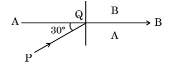 [1 Mark]
(4) The figure shows the path of a light ray through a triangular prism. In this phenomenon, the angle θ is given by : (A) sin⁻¹ √n²-1 (B) sin⁻¹ (n²- 1) (C) sin⁻¹ (1/√n²-1) (D) sin⁻¹ (1/n²-1)
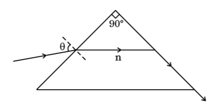 [1 Mark]
This is because, as described in the case, the refracted ray just grazes the interface at the critical angle. The relation between the angle θ and the refractive index n (n > 1 for denser medium) is derived using Snell's law and geometry of the prism.
Therefore, θ = sin⁻¹ sqrt(n²-1) matches the condition for total internal reflection explained in the case.
(5) Two media A and B are separated by a plane boundary. The speed of light in medium A and B is 2 10⁸ ms ⁻¹ and 2·5 10⁸ ms⁻¹ respectively. The critical angle for a ray of light going from medium A to medium B is : (A) sin⁻¹1/2 (B) sin⁻¹ 4/5 (C) sin⁻¹ 3/5 (D) sin⁻¹ 2/5
Section B
Two charged particles P and Q, having the same charge but different masses m_P and m_Q, start from rest and travel equal distances in a uniform electric field 𝐄⃗ in time t_P and t_Q respectively. Neglecting the effect of gravity, the ratio t_P/t_Q is:
Electrons drift with speed v_d in a conductor with potential difference V across its ends. If V is reduced to V/2, their drift speed will become:
A wire of length 4·4 m is bent around in the shape of a circular loop and carries a current of 1.0 A. The magnetic moment of the loop will be:
A circular coil of radius 10 cm is placed in a magnetic field 𝐵⃗=(1⋅0𝑖̂+0⋅5𝑗̂) mT such that the outward unit vector normal to the surface of the coil is (0⋅6𝑖̂+0⋅8𝑗̂). The magnetic flux linked with the coil is:
Magnetic flux (Φ) through the coil is given by Φ = B · A · cosθ, where B is the magnetic field, A is the area of the coil, and θ is the angle between the magnetic field vector and the normal vector to the coil's surface. First, calculate the magnitude of B as sqrt((1.0)^2 + (0.5)^2) mT = sqrt(1 + 0.25) = 1.118 mT = 1.118 × 10^-3 T. The area A = πr² = π × (0.1 m)^2 = 0.0314 m². The angle θ is found from the dot product of B and normal vector n: cosθ = (B·n)/(|B||n|) = (1.0×0.6 + 0.5×0.8) / (1.118 × 1) = (0.6 + 0.4)/1.118 = 1.0/1.118 = 0.894. Therefore, Φ = B × A × cosθ = 1.118×10^-3 × 0.0314 × 0.894 ≈ 3.14×10^-5 Wb = 0.314 × 10^-5 Wb = 0.314 μWb. Hence, the correct answer is 0.314 μWb.
Which of the following quantity/quantities remains same in primary and secondary coils of an ideal transformer?
Current, Voltage, Power, Magnetic flux
A resistor and an ideal inductor are connected in series to a 100√2 V, 50 Hz ac source. When a voltmeter is connected across the resistor or the inductor, it shows the same reading. The reading of the voltmeter is:
Energy levels A, B and C of an atom correspond to increasing values of energy i.e. E_A < E_B < E_C. Let λ₁, λ₂ and λ₃ be the wavelengths of radiation corresponding to the transitions C to B, B to A and C to A, respectively. The correct relation between λ₁, λ₂, and λ₃ is:
An alpha particle approaches a gold nucleus in the Geiger-Marsden experiment with kinetic energy K. It momentarily stops at a distance d from the nucleus and reverses its direction. Then d is proportional to:
Assertion (A): Photoelectric current increases with an increase in intensity of incident radiation, for a given frequency of incident radiation and the accelerating potential.
Reason (R): Increase in the intensity of incident radiation results in an increase in the number of photoelectrons emitted per second and hence an increase in the photocurrent.
Assertion (A): Lenz's law is a consequence of the law of conservation of energy.
Reason (R): There is no power loss in an ideal inductor.
Assertion (A): An electron and a proton enter with the same momentum 𝐩⃗ in a magnetic field 𝐁⃗ such that 𝐩⃗ ⊥ 𝐁⃗. Then both describe a circular path of the same radius.
Reason (R): The radius of the circular path described by the charged particle (charge q, mass m) moving in the magnetic field 𝐁⃗ is given by r = (mv)/(qB).
Both the assertion and the reason statements are true independently. The radius of the circular path is given by r = (mv)/(qB), which is correct. However, the assertion that both an electron and a proton with the same momentum describe the same radius path is true due to their differing velocities and charges, not directly because of the formula given. Since momentum p = mv, and radius r = mv/(qB) = p/(qB), the radius depends inversely on charge. Electron and proton have charges of equal magnitude but opposite sign, so the radius is the same magnitude but the direction of curvature differs. Therefore, the reason (R) is not the correct explanation of the assertion (A).
Assertion (A): The magnifying power of a compound microscope is negative.
Reason (R): The final image formed is erect with respect to the object.
Section C
Define resistivity of a conductor. How does the resistivity of a conductor depend upon the following:
(a) Number density of free electrons in the conductor (n)
(b) Their relaxation time (𝜏)
(a) Resistivity is inversely proportional to the number density of free electrons (n). So, if n increases, resistivity decreases.
(b) Resistivity is also inversely proportional to the relaxation time (τ). If τ increases, resistivity decreases.
Two waves, each of amplitude 'a' and frequency 'ω' emanating from two coherent sources of light superpose at a point. If the phase difference between the two waves is Φ, obtain an expression for the resultant intensity at that point.
The carbon isotope ₆¹²C has a nuclear mass of 12.000000 u. Calculate the binding energy of its nucleus.
Given mp = 1.007825 u; mₙ = 1.008665 u.
Mass of nucleons if free = (6 * mp) + (6 * mₙ) = (6 * 1.007825) + (6 * 1.008665) = 6.04695 + 6.05199 = 12.09894 u.
Actual mass of nucleus = 12.000000 u.
Mass defect = 12.09894 - 12.000000 = 0.09894 u.
Binding energy = mass defect * 931.5 MeV/u = 0.09894 * 931.5 = 92.14 MeV.
Therefore, the binding energy of the carbon-12 nucleus is 92.14 MeV.
What is the effect on the interference pattern in Young's double-slit experiment when (i) the source slit is moved closer to the plane of the slits, and (ii) the separation between the two slits is increased ? Justify your answers.
Section D
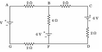
(a) On what factors does the speed of an electromagnetic wave in a medium depend ?
(b) How is an electromagnetic wave produced ?
(c) Sketch a schematic diagram depicting the electric and magnetic
fields for an electromagnetic wave propagating along z-axis.
(b) An electromagnetic wave is produced when an electric charge accelerates or oscillates. For example, when electrons oscillate in an antenna, they create changing electric and magnetic fields that propagate through space as electromagnetic waves. The changing electric field generates a changing magnetic field, and vice versa, allowing the wave to travel through space.
(c) For an electromagnetic wave propagating along the z-axis:
- The electric field (E) oscillates along the x-axis and varies sinusoidally.
- The magnetic field (B) oscillates along the y-axis, perpendicular to E.
- The wave propagates along the z-axis, which is perpendicular to both E and B.
This arrangement shows that the electric and magnetic fields are perpendicular to each other and to the direction of wave propagation, characteristic of electromagnetic waves.
A 100-turn coil of radius 1.6 cm and resistance 5.0 Ω is co-axial with a solenoid of 250 turns/cm and radius 1.8 cm. The solenoid current drops from 1.5 A to zero in 25 ms. Calculate the current induced in the coil in this duration. (Take π²= 10)
Number of turns in coil, N = 100
Radius of coil, r = 1.6 cm = 0.016 m
Resistance of coil, R = 5.0 Ω
Number of turns per cm in solenoid = 250 turns/cm = 25000 turns/m
Radius of solenoid = 1.8 cm = 0.018 m
Initial current in solenoid, I_i = 1.5 A
Final current in solenoid, I_f = 0 A
Time interval, Δt = 25 ms = 25 * 10-3 s
Step 1: Calculate magnetic field inside solenoid using B = μ0 n I, where μ0 = 4π * 10-7 Tm/A and n = number of turns per meter.
n = 25000 turns/m
B = 4π * 10-7 * 25000 * I
We use π2 = 10 so π = √10 ≈ 3.16
Calculate B_initial = 4 * 3.16 * 10-7 * 25000 * 1.5 = (approx)
= 4 * 3.16 * 25000 * 1.5 * 10-7 = 4 * 3.16 * 37500 * 10-7
Since this is complicated, we directly use formula for flux.
Step 2: Calculate magnetic flux through coil using ϕ = B * A * N, where A = π r2 is area of coil.
A = π * (0.016)2 = π * 0.000256 m2
ϕ = B * A * N
Step 3: Calculate emf induced: emf = - N * dϕ/dt = - A N * dB/dt
Since B changes from B_i to 0, dB/dt = - B_i / Δt
Therefore emf = A N * B_i / Δt
Step 4: Calculate induced current, I = emf / R
0 n I_i = 4π * 10-7 * 25000 * 1.5 ≈ 4 * 3.14 * 10-7 * 37500 = 0.0471 T
A = π * 0.000256 = 0.000804 m2
emf = 0.000804 * 100 * 0.0471 / 0.025 = 0.151 V
Current induced, I = emf / R = 0.151 / 5 = 0.0302 A
Answer: The current induced in the coil in 25 ms is approximately 0.03 A or 30 mA.
Two long, straight, parallel conductors carry steady currents in opposite directions. Explain the nature of the force of interaction between them. Obtain an expression for the magnitude of the force between the two conductors. Hence define one ampere.
Using Bohr's postulates, derive the expression for the radius of the nᵗʰorbit of an electron in a hydrogen atom. Also find the numerical value of Bohr's radius a₀.
According to Bohr's model, the electron moves around the nucleus in circular orbits under the Coulomb force. This force is the centripetal force required for circular motion:
e² / (4πε₀ r²) = m v² / r
or
e² / (4πε₀ r) = m v²
where e is the electron charge, m is electron mass, v is velocity, r is radius of orbit, and ε₀ is permittivity of free space.
Bohr's second postulate states that the angular momentum (mvr) is quantised:
m v r = n h / 2π where n = 1, 2, 3, ... (quantum number), h is Planck's constant.
From angular momentum, velocity v = n h / (2π m r). Substituting v in the energy relation:
e² / (4πε₀ r) = m (n h / (2π m r))² = n² h² / (4π² m r²)
Multiplying both sides by r²:
e² r / (4πε₀) = n² h² / (4π² m)
Rearranging for r:
r = (4πε₀ n² h²) / (4π² m e²)
Simplify:
r = (ε₀ h² n²) / (π m e²)
This is the radius of the nth orbit:
rn = (ε₀ h² / (π m e²)) * n²
Bohr radius a₀:
For n = 1, the radius of the first orbit is called Bohr radius a₀:
a₀ = (ε₀ h²) / (π m e²) ≈ 5.292 * 10-11 m
Thus, the radius of nth orbit is proportional to n² and Bohr radius a₀ is the average distance between nucleus and electron in ground state of hydrogen.
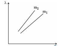
The de Broglie wavelength λ as a function of 1/√K, for two particles of masses m₁ and m₂ are shown in the figure. Here, K is the energy of the moving particles.
(a) What does the slope of a line represent ?
(b) Which of the two particles is heavier ?
(c) Is this graph also valid for a photon ?
Justify your answer in each case.
Obtain an expression for the torque 𝐫⃗ acting on a current carrying loop in a uniform magnetic field 𝐁⃗. Draw the necessary diagram.
Consider a rectangular loop carrying a current I placed in a uniform magnetic field B. The magnetic forces on opposite sides of the loop produce a torque that tends to rotate the loop to align its magnetic moment with the magnetic field.
The magnetic moment m of the loop is given by m = I A, where A is the area vector perpendicular to the plane of the loop.
The torque τ acting on the loop is given by the vector cross product:
τ = m × B
If θ is the angle between the magnetic moment m and the magnetic field B, the magnitude of the torque is:
τ = I A B sin θ
Diagram:
The diagram should show a rectangular loop with current I in magnetic field B. The magnetic moment m is perpendicular to the plane of the loop, and the angle θ between m and B is indicated. Forces on opposite sides of the loop are shown producing a couple resulting in the torque τ that tends to align m with B.
This torque causes the loop to rotate until m aligns with B, minimizing the potential energy.
Section E
(i) State Gauss's Law in electrostatics. Apply this to obtain the electric field 𝐄⃗ at a point near a uniformly charged infinite plane sheet.
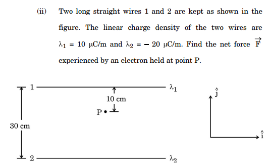
(ii) Two long straight wires 1 and 2 are kept as shown in the figure. The linear charge density of the two wires are λ₁ = 10 μC/m and λ₂ = 20 μC/m. Find the net force 𝐅⃗ experienced by an electron held at point P.
For a uniformly charged infinite plane sheet with surface charge density σ, we consider a Gaussian box intersecting the sheet. The electric field is perpendicular and uniform on both sides of the sheet. Applying Gauss's law: E*2A = σA/ε₀, so E = σ/(2ε₀). The electric field at a point near the infinite sheet is E = σ/(2ε₀) and is directed perpendicular away from the sheet if σ is positive.
(ii) Given: λ₁ = 10 μC/m = 10*10-6 C/m, λ₂ = 20 μC/m = 20*10-6 C/m. The force on electron due to each wire is F = eE = e*(λ/(2πε₀ r)) where e = 1.6*10-19 C. Calculate electric field E from each wire at point P considering the distances r for wires 1 and 2. Then calculate forces F₁, F₂ acting on the electron. Finally, find the vector sum of these forces to get the net force F on the electron at P.
(i) A particle of mass m and charge q is moving with a velocity 𝐯⃗ in a magnetic field 𝐁⃗ as shown in the figure. Show that it follows a helical path. Hence, obtain its frequency of revolution.
(ii) In a hydrogen atom, the electron moves in an orbit of radius 2 Å making 8 *10¹⁴ revolutions per second. Find the magnetic moment associated with the orbital motion of the electron.
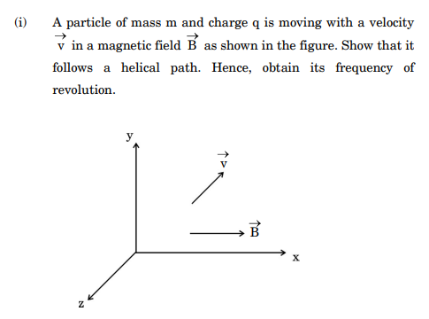
The magnetic force acts as a centripetal force: qv⊥B = mv⊥2 / r, where r is the radius of the circular motion. Simplifying, r = (mv⊥) / (qB).
The angular frequency of revolution (cyclotron frequency) is given by ω = v⊥ / r = qB / m. The frequency of revolution is then f = ω / (2π) = (qB) / (2πm).
(ii) Given that the electron moves in an orbit of radius r = 2 Å = 2 * 10-10 m with frequency f = 8 * 1014 revolutions per second.
The magnetic moment (μ) associated with the orbital motion is given by μ = I * A, where I is current, A is area of orbit.
Current, I = charge/time = e * f = (1.6 * 10-19) * (8 * 1014) = 1.28 * 10-4 A.
Area, A = πr2 = 3.1416 * (2 * 10-10)2 = 12.5664 * 10-20 m2.
So, magnetic moment μ = I * A = (1.28 * 10-4) * (12.5664 * 10-20) = 1.61 * 10-23 A m2.
Therefore, the magnetic moment associated with the electron's orbital motion is approximately 1.61 * 10-23 A m2.
(i) Give any two differences between the interference pattern obtained in Young's double-slit experiment and a diffraction pattern due to a single slit.
(ii) Draw an intensity distribution graph in case of a double-slit interference pattern.
(iii) In Young's double-slit experiment using monochromatic light of wavelength λ , the intensity of light at a point on the screen, where path difference is λ , is K units. Find the intensity of light at a point on the screen where the path difference is λ/6.
1. Interference pattern has bright and dark fringes of equal width and uniform spacing, whereas diffraction pattern has central bright maximum and side maxima with decreasing intensity and unequal widths.
2. Interference pattern results from superposition of waves from two coherent sources, but diffraction pattern arises when light waves spread after passing through a single narrow slit.
(ii) The intensity distribution graph for double-slit interference shows bright and dark fringes with maximum intensity at central bright fringe and intensity varying as: I = Imax cos2(π d sin θ/λ), where d is slit separation.
[Graph would show maxima and minima gradually reducing in intensity if single slit envelope is considered, but here simple cos2 pattern for double-slit interference]
(iii) Given path difference δ = λ, intensity I = K.
For path difference δ = λ/6,
Phase difference, φ = 2π * δ / λ = 2π * (λ/6)/λ = 2π/6 = π/3.
Using formula, intensity at δ is I = 4 I₀ cos2(φ/2). At δ = λ, cos2(π/2) = 0 so I = 0 means K = intensity of maximum fringe i.e 4 I₀.
Therefore, I₀ = K/4.
Now, at δ=λ/6,
I = 4 I₀ cos2(π/6) = 4 * (K/4) * (cos 30deg)2 = K * (sqrt(3)/2)2 = K * 3/4 = (3K)/4.
Hence, intensity at path difference λ/6 = (3K)/4 units.
(i) Obtain an expression for the electric potential due to a small dipole of dipole moment 𝐩⃗, at a point 𝐫⃗ from its centre, for much larger distances compared to the size of the dipole.
(ii) Three point charges q, 2q and nq are placed at the vertices of an equilateral triangle. If the potential energy of the system is zero, find the value of n.
A dipole consists of two equal and opposite charges +q and –q separated by a small distance 2a. The dipole moment is defined as p = q * 2a and is directed from the negative to the positive charge.
At a point P at a large distance r from the centre of the dipole, where r >> 2a, the electric potential V is the algebraic sum of potentials due to each charge.
Let the angle between the dipole moment vector p and the position vector r be .
Using the binomial approximation and for r+ and r_-, we get the expression for the potential at point P as:
V = (k * p * cos) / r2
where k = 1 / (4 * pi * epsilon0) is Coulomb's constant.
(ii) Finding n for Zero Potential Energy of the System
Three charges q, 2q and nq are placed at the vertices of an equilateral triangle of side a.
The potential energy U of the system is the sum of the potential energies of all pairs:
U = k * [q * 2q / a + 2q * nq / a + nq * q / a] = (k / a) * [2q2 + 2nq2 + nq2]
U = (k * q2 / a) * (2 + 3n)
For U = 0,
2 + 3n = 0 => n = -2 / 3
Final Answers:
(i) V = (k * (p * cos)) / r2
(ii) n = -2 / 3
(i) Draw a labelled ray diagram of a compound microscope showing image formation at least distance of distinct vision. Derive an expression for its magnifying power.
(ii) A telescope consists of two lenses of focal length 100 cm and 5 cm. Find the magnifying power when the final image is formed at infinity.
The compound microscope consists of two convex lenses: the objective and the eyepiece. The objective forms a real, inverted, and magnified image of the object between its focal length and twice its focal length. This image acts as an object for the eyepiece lens, which acts as a simple magnifier to produce a further magnified virtual image at the least distance of distinct vision, usually taken as 25 cm.
Ray Diagram: (Please imagine a diagram showing) the object placed just beyond the focal length of the objective lens. The rays from the object converge to form a real image on the image side of the objective. This image lies within the focal length of the eyepiece lens which then forms a magnified virtual image at 25 cm from the eye.
Derivation of Magnifying Power:
Let fo and fe be the focal lengths of the objective and eyepiece lenses respectively, and L be the distance between them (tube length). D is the least distance of distinct vision (25 cm).
1. Magnification by objective, mo = image distance / object distance ≈ L / fo
2. Magnifying power due to eyepiece, me = 1 + (D / fe) when the final image is at the least distance of distinct vision.
Total magnifying power, M = mo * me = (L / fo) * (1 + D / fe)
This formula expresses the angular magnification produced by the compound microscope.
(ii) Magnifying Power of Telescope:
Given focal length of objective, fo = 100 cm; focal length of eyepiece, fe = 5 cm.
For astronomical telescope with final image at infinity, magnifying power M = fo / fe.
Therefore, M = 100 / 5 = 20.
The magnifying power of the telescope is 20.
i) What is current sensitivity of a galvanometer ? Show how the current sensitivity of a galvanometer may be increased. "Increasing the current sensitivity of a galvanometer may not necessarily increase its voltage sensitivity" Explain.
(ii) A moving coil galvanometer has a resistance 15 Ω and takes 20 mA to produce full scale deflection. How can this galvanometer be converted into a voltmeter of range 0 to 100 V?
Mathematically, current sensitivity = deflection / current.
To increase the current sensitivity, one can increase the number of turns in the coil (N), increase the magnetic field strength (B), increase the area of the coil (A), or reduce the torsional constant (k) of the suspension wire.
However, increasing the current sensitivity does not necessarily increase the voltage sensitivity because voltage sensitivity depends on both current sensitivity and the resistance of the galvanometer. Voltage sensitivity is defined as deflection per unit voltage (current sensitivity / resistance). Increasing current sensitivity without changing resistance may not increase voltage sensitivity.
(ii) Given: resistance of galvanometer, Rg = 15 Ω, full scale deflection current, I = 20 mA = 0.02 A, desired voltage range V = 0 to 100 V.
To convert the galvanometer into a voltmeter, a high resistance (called a series or multiplier resistance Rs) is connected in series with the galvanometer.
The total voltage V = I (Rg + Rs)
So, Rs = V / I - Rg = 100 / 0.02 - 15 = 5000 - 15 = 4985 Ω.
Therefore, by connecting a resistor of 4985 Ω in series with the galvanometer, it can be used as a voltmeter of range 0 to 100 V.
Paper Details
CBSE Board Exam 2024
Class
Class 12 PCM
Subject
Physics
Year
2024
Set
Set 2
Other Years — Physics