Class 8 . Mathematics . Ganita Prakash Part II . Exploring Some Geometric Themes
Chapter 4: Exploring Some Geometric Themes
Ch 4
Mathematics
Class 8
Fractals Part-1
Fractals and Self-Similarity
Sierpinski Carpet
Sierpinski Carpet — A square fractal made by repeatedly dividing each remaining square into equal squares and removing the centre one.
Construction and pattern
- Start: The initial square is Step . Divide it into a grid and remove the central square.
- Repeat: Apply the same division and removal to each of the squares that remain.
- At each step: The remaining squares are equal in size; their side lengths become smaller, and removed pieces form square holes.
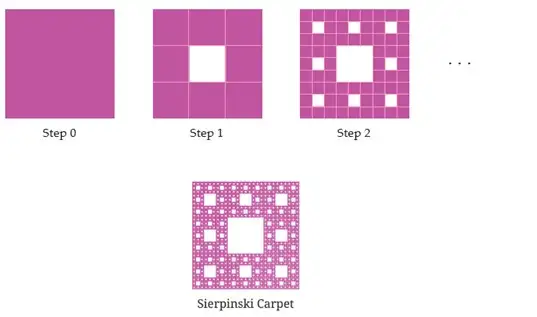
Each remaining square produces smaller remaining squares at the next step. With one starting square, the number remaining at Step is .
At each step, every square remaining from the previous step creates one new hole; all earlier holes remain.
| Step | Remaining squares | Holes |
|---|---|---|
Each step retains of the equal-area parts, so the area is multiplied by at every step.
Find carpet counts and area
- Use the step number and the initial values , .
- Calculate the remaining squares and cumulative holes.
- For starting area , apply the area multiplier for each step.
At Step of the Sierpinski Carpet, how many squares and holes remain, and what is the remaining area if the original area is ?
- Find the remaining squares, holes and area at Step .
- Evaluate the remaining-square formula.
- Evaluate the cumulative-hole formula.
- Find the area when the starting square has area .
Sierpinski Triangle or Gasket
Sierpinski Triangle/Gasket — A triangular fractal made by repeatedly removing the central triangle from subdivisions of the remaining equilateral triangles.
Construction
- Subdivide: Join the midpoints of the sides of an equilateral triangle; this forms identical equilateral triangles.
- Remove: Remove the central triangle, leaving corner triangles.
- Repeat: Apply the same subdivision and removal to each remaining triangle.
Joining the three side midpoints divides an equilateral triangle into identical equilateral triangles: each has side length half the original, and the corner triangles are isosceles with all angles .
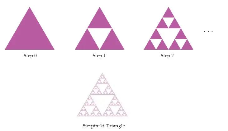
Each remaining triangle produces smaller remaining triangles at the next step. With one starting triangle, the number remaining at Step is .
Each triangle remaining from the previous step creates one new hole, while previous holes remain.
| Step | Remaining triangles | Holes |
|---|---|---|
Each step retains of the equal-area triangles, so the remaining area is multiplied by at every step.
Find gasket counts and area
- Use the step number and the initial values , .
- Calculate the remaining triangles and cumulative holes.
- For starting area , use the retained area ratio at each step.
At Step of the Sierpinski Gasket, how many triangles and holes remain, and what is the remaining area if the original area is ?
- Find the remaining triangles, holes and area at Step .
- Evaluate the remaining-triangle formula.
- Evaluate the cumulative-hole formula.
- Find the remaining area when the starting area is .
For the carpet, calculate the number of remaining squares and holes at Step .
For the gasket, find the remaining area at Step when the starting triangle has area .
At what step does the gasket first have holes?
Quick recap
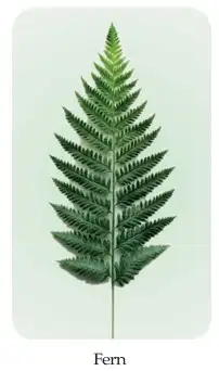
- A fractal repeats the same or a similar pattern at smaller scales.
- The carpet divides each remaining square into parts, removes , and retains .
- For the carpet, , , and .
- The gasket divides each remaining triangle into equal parts, removes , and retains .
- For the gasket, , , and .
- Step is the undivided starting shape; at each next step, earlier holes remain and new holes are added.
Fractals Part-2
The Koch Snowflake
Koch snowflake — A fractal formed by repeatedly replacing every side of an equilateral triangle with a four-segment bump pattern.
Construction and pattern
- Start: Begin with an equilateral triangle.
- Divide: Split each side into three equal parts; raise an equilateral triangle over the middle part and remove its base.
- Replace: Each original segment becomes a bump of four segments, each one-third as long.
- Repeat: Apply the replacement to every boundary segment at each new step.
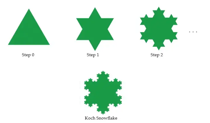
If is the number of replacements made to the starting triangle, each step multiplies the side count by and the perimeter by . For starting side length , the perimeter after replacements is units.
Use these formulas when the starting equilateral triangle has side length .
Find the side count or perimeter
- Treat the starting triangle as step zero and identify the number of replacements, n.
- For the side count, multiply the initial three sides by four for each replacement.
- For the perimeter, multiply the starting perimeter by four-thirds for each replacement.
What are the side count and perimeter after two replacements?
- Find the number of sides and the perimeter after two replacements, starting with side length one unit.
- Substitute into the side-count formula.
- Substitute into the perimeter formula.
How many sides are there after three replacements?
What is the perimeter after one replacement if the starting side length is one unit?
After two replacements, how long is each smallest straight segment if the starting side length is one unit?
Do not multiply the perimeter by four: each side is replaced by four segments that are each one-third as long, so the perimeter factor is .
Fractals in Art
Fractal-like art — Art is fractal-like when forms or patterns repeat in smaller copies at progressively smaller scales.
Examples
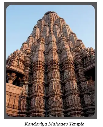
- Kandariya Mahadev Temple: At Khajuraho, Madhya Pradesh; completed around 1025 C.E. Its tall form is echoed by smaller versions of itself.
- Other Indian temples: Fractal-like patterns also occur in temples in Madurai, Hampi, Rameswaram and Varanasi.
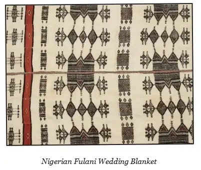
- Nigerian Fulani wedding blankets: Diamond-shaped patterns contain successively smaller diamonds.
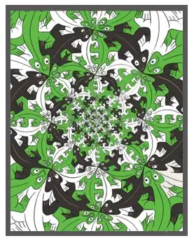
- M.C. Escher: His artwork *Smaller and Smaller* shows the same lizard pattern repeated at progressively smaller scales.
Quick recap
- The Koch snowflake starts with an equilateral triangle.
- Each replacement turns one segment into four segments, each one-third as long.
- After replacements, the side count is and the unit-side perimeter is .
- Fractal-like repetition appears in the Kandariya Mahadev Temple and other Indian temples.
- Nigerian Fulani wedding blankets use nested diamond patterns.
- M.C. Escher's *Smaller and Smaller* repeats a lizard pattern at smaller scales.
Visualising Solids
Shapes formed by cutting corners
Results of corner cuts
- Square: Joining the midpoints of adjacent sides cuts off four congruent right-isosceles triangles; the middle region is a square.
- Reassembly: The four corner triangles can be rearranged into a square of side , where is the original square’s side.
- Equilateral triangle: Cutting each corner at the one-third marks leaves a regular hexagon.
- Square divided into thirds: Cutting off each corner at the one-third marks leaves an octagon; it is not regular.
Profiles of solids
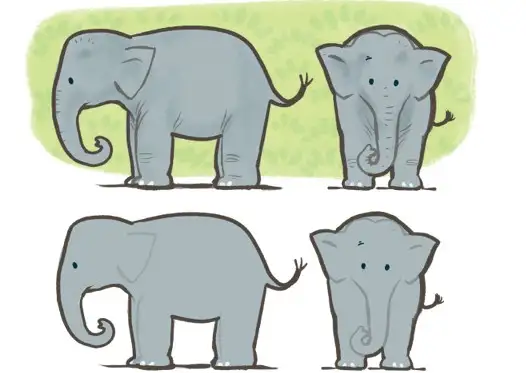
Profile — A profile is the outline of a solid as seen from a particular viewpoint.
A solid can have different profiles when viewed from different directions; the profile describes its outline, not the whole solid.
Use the solid and viewing direction together to determine the outline.
| Profile(s) | Solid and viewpoint |
|---|---|
| Square | A cube viewed face-on |
| Circle | A sphere from any direction; a cylinder viewed at an end; or a cone viewed from above |
| Triangle | A cone viewed from the side, or a triangular prism viewed at its triangular end |
| Rectangle and circle | A cylinder viewed from the side and then at an end |
| Circle and triangle | A cone viewed from above and then from the side |
| Rectangle and triangle | A triangular prism viewed from the side and then at a triangular end |
| Trapezium and circle | A frustum of a cone viewed from the side and then from above |
| Pentagon and rectangle | A pentagonal prism viewed at an end and then from the side |
Choosing a solid
- Many possibilities: A profile condition does not usually determine one unique solid; several solids or viewpoints may give the same outline.
- Useful approach: Match each required outline to a viewpoint, then check whether one solid can produce all the outlines.
Predicting a solid’s profile
- Identify the viewing direction, such as from the side, end, or above.
- Imagine the solid’s outline from that direction, ignoring depth.
- Repeat from another direction if the question asks for multiple profiles.
Find a solid with a circular profile from one viewpoint and a rectangular profile from another.
- Consider a cylinder and view it along its circular axis.
- Turn to a side view, perpendicular to that axis.
- So one solid gives the required circular and rectangular profiles.
Give a solid that has a triangular profile from one direction and a rectangular profile from another.
Give a solid with a circular profile from above and a trapezium-shaped profile from the side.
Which solid can have a pentagonal profile from one view and a rectangular profile from another?
Quick recap
- A profile is the outline of a solid seen from a particular viewpoint.
- Changing the viewpoint can change the profile without changing the solid.
- Cylinders give circular end views and rectangular side views.
- Cones give circular top views and triangular side profiles.
- Prisms can give polygonal end profiles and rectangular side profiles.
- Cutting the corners of a triangle at its trisection marks leaves a regular hexagon.
Visualizing Solids – Making Solid Part-1
Solids and Their Parts
A cube or cuboid has faces, edges and vertices.
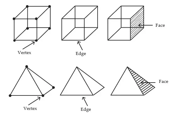
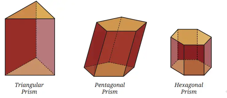
Prisms and Pyramids
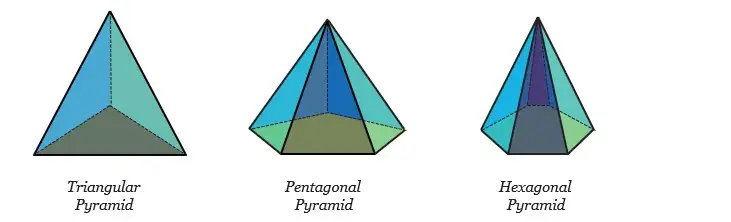
Pyramid — A pyramid has a polygonal base and one point outside the base joined to every base vertex.
| Point | Prism | Pyramid |
|---|---|---|
| Main faces | Two congruent polygonal ends | One polygonal base |
| Other faces | Parallelograms | Triangles meeting at one point |
| Name depends on | Shape of the matching ends | Shape of the base |
Use these counts when each end is an -sided polygon.
The -sided prism has polygonal faces and side faces; its two ends contribute vertices and edges, while the joining edges contribute another edges.
Use these counts when the base is an -sided polygon.
An -sided pyramid has one base and triangular side faces. Its base vertices plus the apex give vertices.
Counting faces, edges and vertices
- Identify whether the solid is a prism or a pyramid, and count the polygon sides as .
- Substitute into the matching formulas for faces, edges and vertices.
- Check that each count is a whole number and fits the solid’s structure.
Find the faces, edges and vertices of a 10-sided prism and a 10-sided pyramid.
- Find the faces, edges and vertices of a 10-sided prism and a 10-sided pyramid.
- For the prism, substitute into its count formulas.
- For the pyramid, substitute into its count formulas.
Nets of Solids
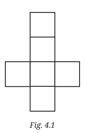
How many faces, edges and vertices does a hexagonal prism have?
How many faces, edges and vertices does a square pyramid have?
What must be true of a six-square arrangement to be a net of a cube?
Quick recap
- A face is a flat surface, an edge is where faces meet, and a vertex is where edges meet.
- An -sided prism has faces, edges and vertices.
- An -sided pyramid has faces, edges and vertices.
- A prism has two congruent polygonal ends; a pyramid has one polygonal base and an apex.
- A net is a flat arrangement of faces that folds into a solid; a cube net has six equal squares.
Visualizing Solids – Making Solid Part-2
Practical Aspects of Making a Solid
Net — A net is a flat arrangement of a solid’s faces that can be folded to form the solid.
Making a Physical Model
- Material: Use material sturdy enough to hold the solid’s shape.
- Joining faces: Tape or extra flaps can attach adjacent faces when making the model.
- Net vs. model: Supporting flaps used to join faces are not included in the net.
Cube and Cuboid Nets
Cube net — A cube net is an arrangement of six connected squares that folds into the six faces of a cube.
Checking and Counting Cube Nets
- Valid net: The squares must fold without overlapping or leaving a cube face uncovered.
- Number of nets: A cube has 11 distinct nets.
- Same net: Arrangements differing only by a rotation or a flip count as the same net.
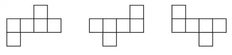
Cuboid net — A cuboid net has six rectangles: two matching rectangles for each pair of opposite faces.
Cuboid Face Sizes
- Example: Side lengths 5 cm, 3 cm and 1 cm give two faces each of sizes , and cm.
- Arrangement: Place the six rectangles so that they fold into the cuboid with matching pairs opposite each other.
Regular Tetrahedron
Regular tetrahedron — A regular tetrahedron is a solid whose four faces are equilateral triangles.
Tetrahedron Nets
- Faces: A net uses four connected equilateral triangles that fold into the solid.
- Number of nets: A regular tetrahedron has 2 distinct nets.
- Check: Fold a cutout to see whether the triangles meet without gaps or overlaps.
Cylinder Net
Cylinder net — A cylinder net consists of one rectangle and two equal circles.
Cylinder Net Dimensions
- Rectangle height: It equals the cylinder’s height.
- Rectangle length: It equals the circumference of a circular base.
- Faces: The circles form the bases, and the rectangle forms the curved surface.
For base radius and cylinder height , the rectangle’s sides are the base circumference and the cylinder height.
What are the dimensions of the rectangle in the cylinder’s net?
- Find the rectangular part of the net for a cylinder with radius 3 cm and height 8 cm.
- Calculate the circumference of its base.
- Pair the circumference with the cylinder’s height.
Cone Net
Cone net — A cone net consists of its circular base and a circular sector that forms the curved surface.
Cone Sector
- Sector radius: It equals the cone’s slant height.
- Sector arc: Its length equals the circumference of the cone’s base.
- Unrolling: The curved surface becomes a portion of a circle, not a full circle.
For slant height and base radius , the sector radius is and its arc matches the base circumference.
Other Solids and Their Nets
Square Pyramid and Triangular Prism
- Square pyramid net: One square base and four triangular side faces; the triangles fold up to meet at one apex.
- Triangular prism net: Three rectangular side faces and two triangular ends.
- Check: Fold a cutout to verify that the faces meet correctly without gaps or overlaps.
Octahedron and Dodecahedron
Octahedron — An octahedron is formed by joining two square pyramids at their square bases.
Octahedron and Dodecahedron Facts
- Octahedron faces: It has eight triangular faces; if they are equilateral, its net uses eight equilateral triangles.
- Octahedron nets: It has 11 distinct nets.
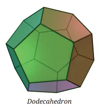
- Dodecahedron: It is a solid whose faces are all pentagons.
- Dodecahedron nets: It has 43,380 distinct nets.
Can a Sphere Have a Flat Net?
Sphere net — A sphere has no exact flat net that wraps its surface without distortion.
- Reason: A flat cutout cannot cover a sphere exactly without wrinkles, gaps or overlaps.
What face rectangles are needed for a cuboid with side lengths 6 cm, 3 cm and 2 cm?
A cylinder has radius 2 cm and height 5 cm. What are the dimensions of the rectangular part of its net?
How many distinct nets are there for a cube and a regular tetrahedron?
Quick recap
- A net is a flat arrangement of a solid’s faces; joining flaps are not part of the net.
- A cube has 11 distinct nets, while a regular tetrahedron has 2.
- Cuboid nets use two matching rectangles for each pair of opposite faces.
- A cylinder net has a rectangle and two equal circles; the rectangle length equals the base circumference.
- A cone net has a circular base and a sector with radius equal to the slant height.
- An octahedron has 11 distinct nets; a dodecahedron has all pentagonal faces and 43,380 distinct nets.
- A sphere has no exact flat net that wraps its surface without distortion.
Visualizing Solids – Shortest Path on a Cube
Finding a Shortest Path on a Cuboid
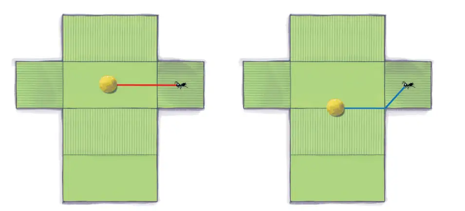
Shortest path on a surface — The shortest path between two points on a cuboid is the shortest route connecting them while staying on its surface.
Unfolding the relevant faces preserves path length. On the flat net, the shortest path between two points is a straight segment, provided it stays on the net and folds back to a valid surface path.
Key points
- Unfolding: A path on the cuboid becomes an equal-length path on a flat net, and vice versa.
- Validity: A straight segment that goes outside the net does not represent a path on the cuboid.
- Different nets: How the cuboid is unfolded matters; different unfoldings can give different candidate lengths.
- Shortest route: Compare the lengths of all relevant valid paths and choose the least.
In a right-angled triangle, the square of the hypotenuse equals the sum of the squares of the other two sides.
Use this formula when the straight path is the hypotenuse of a right triangle on the net.
Method for finding the shortest surface path
- Unfold the faces that a possible route could cross into a net.
- Mark the two points on the net and draw the straight segment between them.
- Reject a segment that leaves the net or cannot fold back to a surface path.
- Calculate the lengths of valid candidates from different unfoldings and select the least.
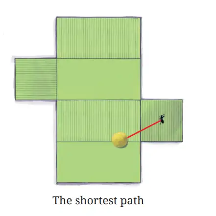
Find the path length represented by the valid unfolding with perpendicular sides 24 cm and 32 cm.
- On a valid unfolding, the path is the diagonal of a rectangle with sides 24 cm and 32 cm.
- Apply the Baudhāyana Theorem and add the squares.
- Take the positive square root to find the path length.
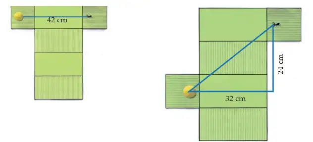
Do not choose the shortest-looking line on just one net: it may leave the net or be longer than a valid route from another unfolding.
A valid unfolded route forms the diagonal of a rectangle with sides 9 cm and 12 cm. Find its length.
Two valid unfoldings give candidate diagonals with perpendicular sides 8 cm and 15 cm, or 12 cm and 12 cm. Which candidate is shorter?
Quick recap
- Unfolding turns a surface route into an equal-length path on a flat net.
- On a net, the shortest path is a straight segment, if it stays within the net and folds back onto the cuboid.
- A straight segment outside a net is not a valid surface path.
- Different unfoldings can give different valid candidate path lengths.
- Use the Baudhāyana Theorem for right-triangle diagonals, then compare all valid candidates.
Visualizing Solids on a Plan Surface Part-1
Representing solids on a plane
Ways to represent a solid
- Drawings: A plane drawing can record or communicate information about a three-dimensional object, including for design and construction.
- Nets: A net represents a solid on a plane, but may be hard to visualise as a solid without cutting it out and folding it.
- Projections: Projecting an object onto a plane is another way to represent it and show its profile from a particular direction.
Projection of a point and an object
Orthogonal projection of a point — For a point and plane , the foot of the perpendicular from to is the projection of on .
The projection of an object on a plane consists of the projections of all its points onto that plane.
The segment joining a point to its projection is perpendicular to the plane.
Where does project on plane ?
- The perpendicular from to plane meets it at .
- The point where the perpendicular meets the plane is the projection.
Length of a projected line segment
Projected length — The projected length of a segment is the distance between the projections of its endpoints.
A segment’s projection is no longer than the segment. It has the same length when the segment is parallel to the plane; a segment perpendicular to the plane projects to a point.
Equality holds when the segment is parallel to the plane.
Find its projected length.
- A segment of length units is parallel to the plane, so its projection keeps the same length.
- Substitute the given length.
Projections of plane shapes
A polygon’s projection is formed from the projections of its sides; parallel sides remain parallel unless they collapse to a point.
What general quadrilateral can a square project to when its sides do not collapse?
- A square has two pairs of opposite parallel sides.
- Projection preserves parallelism; if the image is a quadrilateral, both opposite-side pairs remain parallel.
Projections of solids and three views
A solid’s projection depends on the viewing direction and does not show all its three-dimensional information.
Three mutually perpendicular views — Three standard projections show an object on vertical, horizontal, and side planes that are mutually perpendicular.
| Projection plane | View | Direction |
|---|---|---|
| Vertical plane | Front view | From the front |
| Horizontal plane | Top view | From above |
| Side plane | Side view | From the side |
Reading the views
- Front view: Projection onto the vertical plane.
- Top view: Projection onto the horizontal plane.
- Side view: Projection onto the side plane.
- Purpose: Combining these profiles gives more information than a single projection.
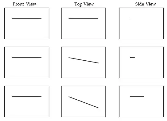
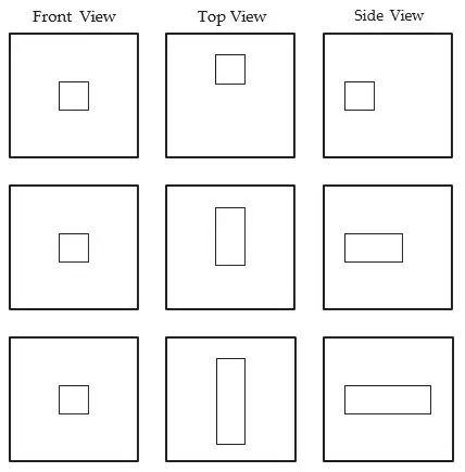
What are the front, top, and side views of the aligned cube?
- A cube is aligned with the three viewing planes; each view looks directly at one square face.
A segment of length cm is perpendicular to a plane. Find its projected length.
Can two different solids have the same front view? Explain briefly.
Quick recap
- A net is another plane representation of a solid, but folding may be needed to visualise the solid.
- A point projects to the foot of its perpendicular on the plane; an object’s projection combines the projections of all its points.
- A segment’s projected length satisfies ; it is unchanged when parallel to the plane and becomes a point when perpendicular.
- A polygon’s projection is built from projected sides; a parallelogram remains one if its projected outline is a quadrilateral.
- Different solids can have the same projection, so one view may not identify a solid uniquely.
- The three standard views are front, top, and side views on mutually perpendicular planes.
Visualizing Solids on a Plan Surface Part-2
Front, Top and Side Views
Orthographic projection — A projection formed by projecting an object onto a plane along lines perpendicular to that plane.
Here, is the solid and , and are the vertical, horizontal and side planes.
Drawing a view
- Choose the view and the plane receiving the projection.
- Look from the specified direction and draw the outline.
- Show lengths parallel to the plane at their true size.
Find the three views of the cuboid.
- Identify the cuboid’s three dimensions.
- Use length and height for the front view, and length and width for the top view.
- Use width and height for the side view.
Shadows as Projections
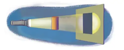
Shadow — A shadow is the shape formed on a plane when an object blocks light from reaching it.
How shadows relate to projections
- Similar shape: A shadow’s shape is generally quite similar to the object’s projection on the plane.
- Nearby light: The shadow may be scaled up, stretched or slightly distorted, depending on the light source’s distance and how the object is held.
- Distant light: As the source moves farther away, its shadow approaches the projection formed by parallel rays.
- Sunlight: When sunlight is perpendicular to a plane, the shadow on that plane is indistinguishable from the projection.
- Parallelogram: Its projection remains a parallelogram, though its size and angles may change.
The projections of a pair of parallel lines remain parallel. Hence, both pairs of opposite sides of a parallelogram remain parallel in its projection.
Use this property when sketching projections of objects with parallel edges.
Sketching a projected shape
- Identify the plane receiving the projection.
- Project the outline onto the plane along parallel rays.
- Keep parallel edges parallel in the drawing.
What shape does a parallelogram’s projection make?
- A parallelogram has two pairs of parallel opposite sides.
- Projection preserves the parallelism of both pairs.
Views of Cube Arrangements
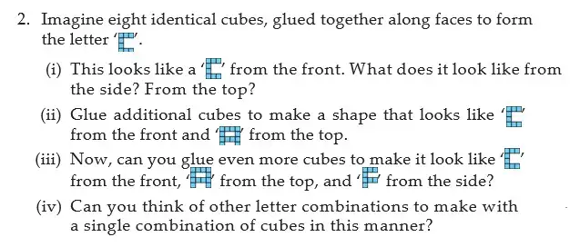
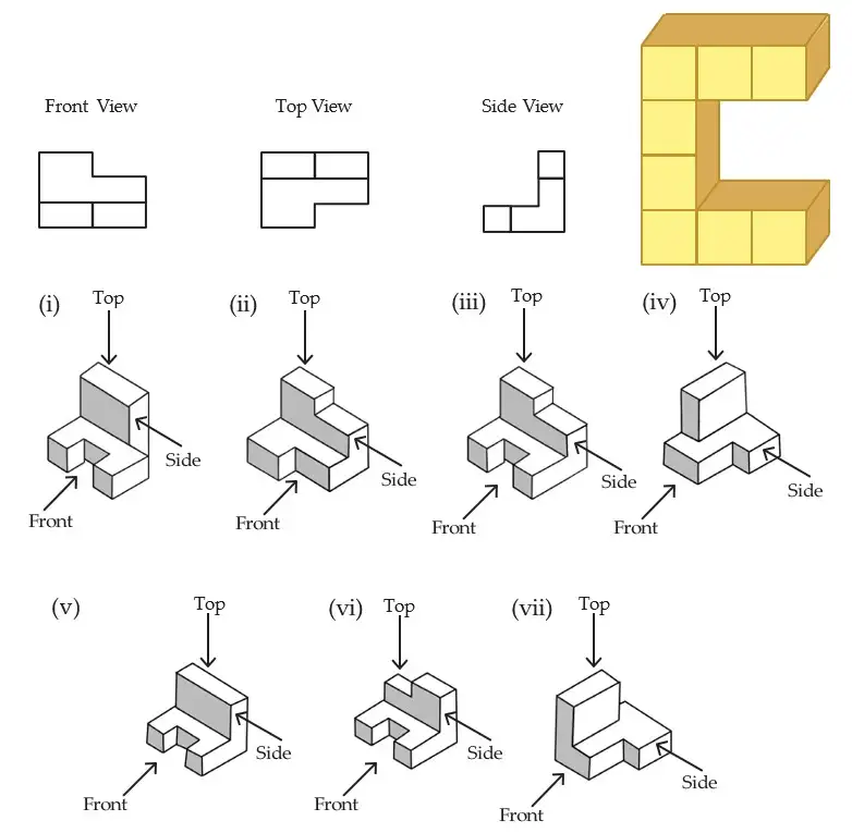
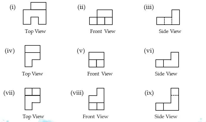
Cube-stack projections — The views of identical cubes show their occupied positions and the outlines of their heights from different directions.
Reading views of cube stacks
- Top view: Shows which ground positions contain cubes, but does not show stack heights.
- Front view: Shows the maximum stack height at each left-to-right position.
- Side view: Shows the maximum stack height at each front-to-back position.
- Reconstruction: The views constrain the arrangement but may not determine a unique solid; hidden cubes may be needed.
- Cube projection: Depending on its orientation, a cube’s outline can be a square, rectangle or hexagon.
Add the heights of all vertical stacks to find the number of cubes.
Counting cubes in an arrangement
- Identify each occupied ground position.
- Determine the height of the stack at each position.
- Add the heights to find the total number of cubes.
How many cubes are in stacks of heights 2, 1, 1 and 3?
- List the heights of the four vertical stacks.
- Add the stack heights.
A cylinder stands upright on a flat surface. Describe its top, front and side views.
Under parallel projection, what happens to the opposite sides of a parallelogram?
An arrangement has vertical stacks of heights 3, 2, 2 and 1. How many cubes are there?
Quick recap
- Front, top and side views are projections onto vertical, horizontal and side planes.
- A segment parallel to the viewing plane keeps its true length; an oblique segment appears shorter.
- A shadow is generally similar in shape to a projection, but may be scaled, stretched or slightly distorted.
- A distant light source gives a projection-like shadow; perpendicular sunlight casts a shadow indistinguishable from a projection.
- Parallel lines remain parallel under projection, so a parallelogram remains a parallelogram.
- Top views show occupied ground positions; front and side views show heights from their respective directions.
- Count cubes by adding the heights of all vertical stacks.
Visualizing Solids - Isometric Projections
Isometric Projection
Parallel lines project to parallel lines, and equal unit lengths along the three principal directions have equal projected lengths.
Here, , , and are projected unit lengths along the length, depth, and height axes.
Recognizing an isometric projection
- Identify the solid’s length, depth, and height directions.
- Compare the projected lengths of one-unit edges along all three directions.
- If these lengths are equal, the projection is isometric.
How can you tell whether a projected cube drawing is isometric?
- A cube drawing has equal projected unit edges along length, depth, and height.
- It meets the equal-length condition for an isometric projection.
- Its outline in this view is a regular hexagon.
Isometric Grids and Drawing Solids
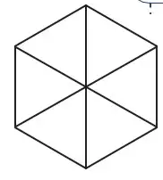
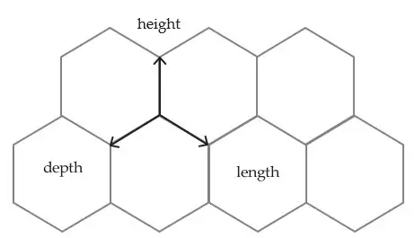
The three families of parallel edges in a solid project to three families of parallel grid lines, and equal unit steps along the three axes have equal projected lengths.
Equal unit steps along length, depth, and height have equal projected lengths.
Drawing a solid on an isometric grid
- Choose the grid direction for each of length, depth, and height.
- Draw each edge by counting the required unit steps along its axis.
- For joined cubes, show the visible outer edges and omit or erase edges hidden inside the solid.
- Check whether each edge runs in the chosen axis direction or its opposite before drawing it.
How do you draw a cube of side two grid units on an isometric grid?
- A cube with side length two grid units needs two units along each axis.
- Draw the three edges from one corner, then complete the parallel edges.
- Remove internal hidden edges or show hidden edges dashed if needed.
Do not switch the slanting directions for length and depth midway through a drawing: keep the grid-to-axis mapping consistent.
Reading unusual solid drawings
- Direction check: To draw an edge, identify its axis and whether it goes in the positive or opposite direction on the grid.
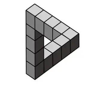
- Impossible figures: A drawing may look locally like connected cubes but still be impossible to build as one solid; test whether its depth and direction relationships can all coexist.
- Impossible triangle: The triangular cube arrangement is an illusion, not a model that can be built from actual cubes. Its isometric drawing works because the projected edges suggest a consistent three-dimensional structure.
A row of four unit cubes is placed along the depth axis. How should it be drawn on an isometric grid?
Why are isometric grids effective for communicating a solid’s shape?
Can the impossible triangular cube arrangement be built from actual cubes? Why does its drawing create an illusion?
- Isometric projection: Unit lengths along length, depth, and height project equally.
- Grid mapping: Height is vertical, depth follows the slash direction, and length follows the backslash direction.
- Drawing solids: Count grid units, keep each axis direction consistent, and check which edges are hidden.
Quick recap
- An isometric projection gives equal projected lengths to unit steps along the three principal axes.
- A cube’s isometric representation has a regular hexagonal outline.
- On the grid, height is vertical, depth uses the slash direction, and length uses the backslash direction.
- Parallel edges project to parallel grid lines.
- Draw solids by counting grid units and keeping the axis mapping consistent.
- Some isometric drawings create convincing illusions of solids that cannot actually be built.
Summary
Fractals
- Fractals: Geometric shapes with patterns that repeat at smaller and smaller scales.
- Examples: The Sierpinski Carpet, Sierpinski Gasket, and Koch Snowflake are mathematical fractals; self-similar patterns also occur in nature and art.
Nets of Solids
- Nets: A net is a flat shape formed by unfolding a solid onto a plane.
- Making solids: Suitable nets can be folded to form solids such as cubes, prisms, pyramids, cylinders, and cones.
Shortest Paths on a Cuboid
- Surface paths: A route between two points on a cuboid must stay on its surface.
- Unfolding: A suitable net turns a surface route into a path in the plane, where straight-line distances can be compared.
Views and Isometric Projections
A triangular prism is to be made from a net. What types of faces must the net contain?
On a suitable cuboid net, two points are opposite corners of a rectangle measuring 5 cm by 12 cm. Find the straight-line path length on that net.
- Fractals: Repeated geometric operations create self-similar patterns.
- Nets and paths: Nets fold into solids; unfolding faces turns a surface path into a straight-line problem.
- Views: Front, top, and side views are projections; isometric drawings represent three dimensions.
Quick recap
- Fractals are self-similar patterns produced by repeating geometric operations.
- The Sierpinski Carpet, Sierpinski Gasket, and Koch Snowflake are examples of fractals.
- A suitable net folds into a solid and contains all its faces.
- Unfold cuboid faces to turn a surface route into a straight line, then compare suitable nets.
- Front, top, and side views represent an object on planes.
- Isometric projection represents the three edge directions with equal lengths in the drawing.
Formula sheet
Mathematics — ALL CHAPTERS
1
A Square And A Cube
2
Power Play
3
A Story of Numbers
4
Quadrilaterals
5
Number Play
6
We Distribute, Yet Things Multiply
7
Proportional Reasoning-1
1
Fractions in Disguise
2
The Baudhayana-Pythagoras Theorem
3
Proportional Reasoning-2
4
Exploring Some Geometric Themes
5
Tales by Dots and Lines
6
Algebra Play
7
Area