NEET UG . NEET Physics . Physics . Alternating Current
Chapter 22: Alternating Current
Ch 22
NEET Physics
NEET UG
AC Voltage Applied to a Resistor
Alternating and Direct Current
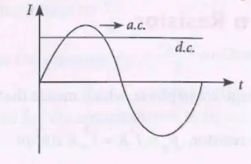
Fundamentals of Alternating Current
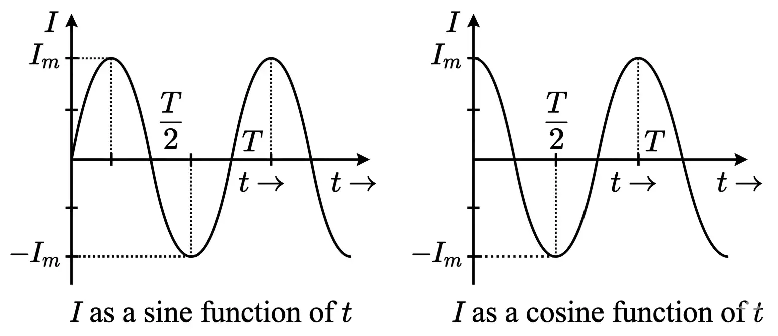
Current may be written in sine or cosine form; angular frequency is related to period and frequency.
Average (mean) value of AC — The equivalent DC value that sends the same charge through a circuit in the same time; for sinusoidal AC, the mean is calculated over a half-cycle.
For sinusoidal current, the mean value over one half-cycle is proportional to the peak current.
Root mean square (rms) value — The DC value that produces the same heat in a resistor, over the same time, as the AC current.
For sinusoidal current, the rms value is the peak value divided by .
Phase and Phase Difference
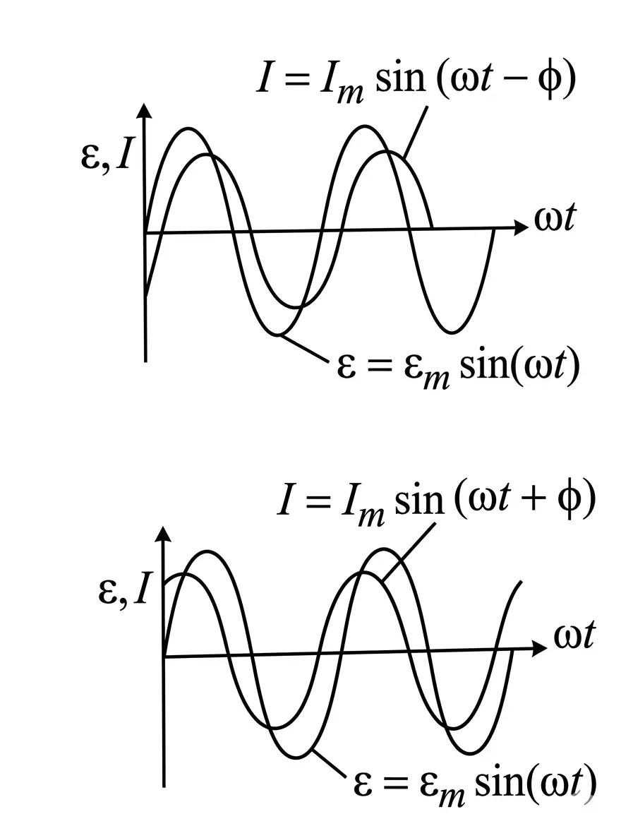
Phase difference — The difference between the phases of two alternating quantities, indicating how far one leads or lags the other.
AC Voltage Applied to a Resistor
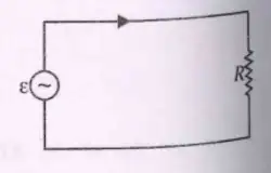
Instantaneous power varies during the cycle and is dissipated as heat in the resistor.
Average power in a resistor can be expressed using peak or rms current and voltage.
What are the average and rms values of a sinusoidal current?
State the phase relation and average power for an AC circuit containing only a resistor.
Quick recap
- AC changes magnitude and reverses direction periodically; DC maintains constant magnitude and direction.
- Transformers make AC voltage easy and efficient to convert between voltage levels.
- For a sinusoidal current, ; the half-cycle mean is .
- The rms current is and represents the heating-equivalent DC current.
- In a pure resistor, current and voltage are in phase.
- Average resistor power is .
Representation of AC Current and Voltage by Rotating Vectors-Phasors
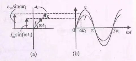
Phasor — A phasor is a vector rotating about the origin at angular speed , used to represent the phase relationship between alternating voltage and current.
Phasors and AC quantities
- Not vectors: The voltage and current are scalar quantities; their rotating phasors represent them.
- Sinusoidal values: The vertical components of the voltage and current phasors vary as and .
- Angular speed: Both phasors rotate with angular speed .
The instantaneous values are the vertical components of their rotating phasors.
AC Source Connected to a Resistor
- Same direction: In a circuit containing an AC source and a resistor, the voltage and current phasors point in the same direction.
- Phase relation: Voltage and current are in phase; their phase difference is .
- Waveforms: The voltage and current sinusoidal graphs therefore reach corresponding values together.
Quick recap
- A phasor rotates about the origin at angular speed and represents phase relationships.
- Voltage and current are scalar quantities, not vectors.
- Their instantaneous values are the vertical components of the rotating phasors.
- For a resistor, voltage and current phasors point in the same direction.
- In a resistor circuit, voltage and current are in phase with phase difference .
AC Voltage Applied to an Inductor
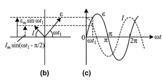
Current and Inductive Reactance
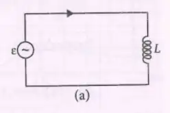
AC response of a pure inductor
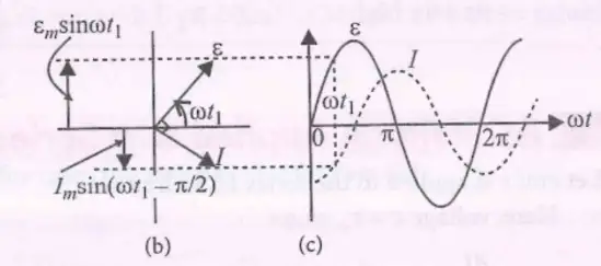
- Voltage: If the applied voltage is , the current is .
- Phase: Current lags the voltage by (a quarter cycle) in a pure inductive load.
- Current amplitude: ; increasing angular frequency or inductance reduces the current amplitude.
Inductive reactance — The opposition an inductor offers to alternating current is called inductive reactance, denoted by ; it is analogous to resistance.
Here, is frequency and is inductance.
Power in a Pure Inductor
Power varies with time and alternates in sign during the cycle.
Since the average of over a complete cycle is zero, a pure inductor consumes zero average power.
What is inductive reactance, and how is it related to frequency?
What is the phase relation between voltage and current in a pure inductor?
What is the average power supplied to a pure inductor over one complete cycle?
Quick recap
- For an applied voltage , current is .
- Current in a pure inductor lags voltage by .
- Inductive reactance is .
- Current amplitude is .
- Instantaneous power varies as .
- Average power supplied to a pure inductor over a complete cycle is zero.
AC Voltage Applied to a Capacitor
Current and Voltage in a Capacitor
It plays the role of resistance in an AC circuit and is measured in ohms.
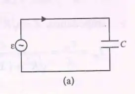
Do not say voltage leads current in a capacitive load: current leads voltage by .
Power in a Capacitor
The instantaneous power alternates between positive and negative values over each cycle.
The mean of over a complete cycle is zero, so an ideal capacitor consumes no average power.
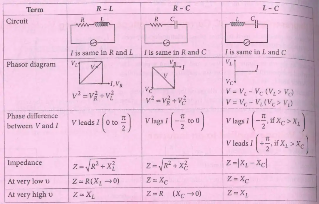
Combinations of R, L and C in AC Circuits
Quick recap
- For a capacitor, when .
- Current leads voltage by in a capacitive load.
- Capacitive reactance is .
- Current amplitude is .
- The average power consumed by an ideal capacitor over a cycle is zero.
- Series R–L, R–C and L–C circuits can be compared using their phasors and frequency-dependent impedance.
Ac Voltage Applied to a Series LCR Circuit
Series LCR Circuit
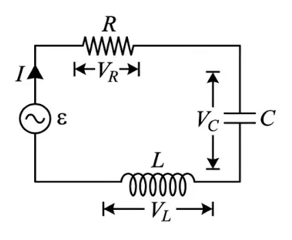
Voltage Phasors
- Opposite directions: The capacitor and inductor voltage phasors lie along the same line but point in opposite directions.
- Resultant voltage: The resistor voltage is perpendicular to the net reactive voltage, so the source voltage follows a right-triangle relation.
Impedance is the effective opposition to alternating current in the series circuit.
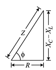
Phase and Lead–Lag Relationship
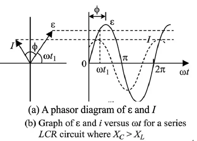
Resonance in a Series LCR Circuit
Use either angular frequency or ordinary frequency for the resonance condition.
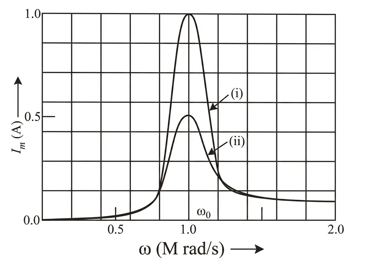
Resonance Example
- Given: , and give .
- Compare currents: For and , resonance currents are and respectively.
- Conclusion: At the same applied emf, halving resistance doubles the resonance current amplitude.
Quality Factor
Equivalent forms of the quality factor at resonance.
State the resonance condition and the current amplitude at resonance.
How does current relate in phase to the source voltage when ?
Write the expression for the quality factor of a series LCR circuit.
Quick recap
- A series LCR circuit has impedance .
- The current amplitude is .
- When , the circuit is capacitive and current leads; when , it is inductive and current lags.
- Resonance occurs at , where impedance is and current is maximum.
- The resonant angular frequency is .
- The quality factor is ; higher gives better tuning.
Power in AC Circuit :The Power Factor
Power in an AC Circuit
Phase difference — The voltage and current in an AC circuit may differ in phase by an angle .
AC voltage, current and phase
- Voltage and current: and .
- Current amplitude: .
- Phase angle: , where and are capacitive and inductive reactances.
The oscillating term averages to zero over a complete cycle. The power factor is .
| Circuit | Phase and power factor | Power behaviour |
|---|---|---|
| Pure resistor | , so | Maximum power is dissipated in the resistor. |
| Pure inductor or capacitor | , so | No average power is dissipated although current flows; this is called wattless current. |
| Series LCR circuit | Average power is dissipated only in the resistor, even when the phase difference is non-zero. | |
| LCR circuit at resonance | As stated in this lecture, and | Power is maximum: . |
Choke Coil
Choke coil — A choke coil is an inductor with some resistance, used to reduce AC current with little power loss.
Use and operation
- Use: It reduces current without the large power loss caused by using a resistor; choke coils are used in tube lights.
- Why effective: Inductive reactance gives the coil a large impedance, while its small resistance keeps absorbed power low.
When , the power factor is approximately .
LC Oscillations
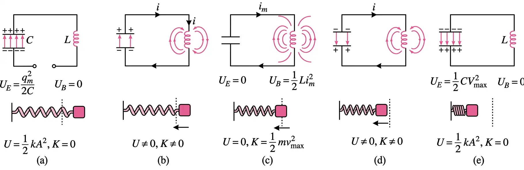
LC oscillations — LC oscillations are the repeated exchange of energy between a capacitor's electric field and an inductor's magnetic field in an ideal circuit with no resistance.
Energy exchange
- Discharging capacitor: As the capacitor discharges, current increases and builds magnetic energy in the inductor.
- Maximum current: Energy is entirely magnetic: .
- Ideal circuit: Electric and magnetic energies transform into each other while total energy remains constant.
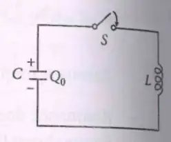
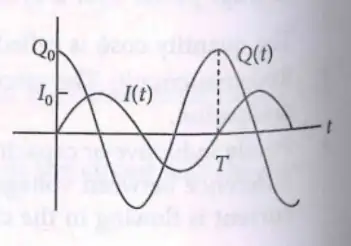
The charge oscillates harmonically; is its maximum value and is the phase.
Since , the current amplitude is . For and , .
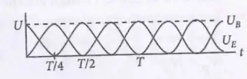
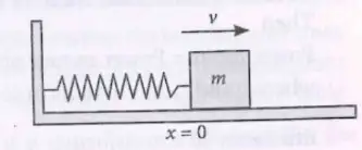
| Point | LC circuit | Spring–mass system |
|---|---|---|
| Oscillating quantities | Charge and current | Displacement and velocity |
| Energy exchange | Capacitor electric energy ↔ inductor magnetic energy | Spring potential energy ↔ kinetic energy |
| Ideal condition | No circuit resistance | No friction |
What is the power factor, and how is average power expressed?
Why is average power zero in a purely inductive or capacitive circuit?
Quick recap
- Average AC power is ; is the power factor.
- A pure resistor has ; pure inductors and capacitors have zero average power and wattless current.
- At resonance, this lecture states , , and power is maximum in the resistor.
- A choke coil reduces current through inductive reactance while keeping absorbed power small.
- An ideal LC circuit exchanges energy between the capacitor and inductor while total energy remains constant.
- The general charge solution is ; zero initial current and maximum initial charge give .
- LC oscillations have , and charge and current are a quarter-cycle out of phase.
Transformers
Transformer: Principle and Ideal Relation
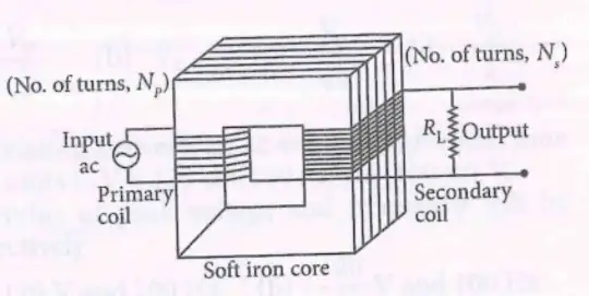
- Principle: A transformer works by mutual induction between its primary and secondary coils.
- Ideal relation: , where is the transformation ratio.
Step-Up Transformer
The voltage ratio equals the turns ratio.
Step-Down Transformer
The secondary-to-primary voltage ratio is less than one.
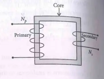
Power, Efficiency and Energy Losses
Efficiency is output power divided by input power, expressed as a percentage.
| Loss | Cause | How to reduce it |
|---|---|---|
| Copper loss | Joule heating in the resistances of the primary and secondary coils. | Use thick copper wires. |
| Hysteresis loss | Repeated magnetisation and demagnetisation of the core. | Use soft iron, which has a small hysteresis-loop area. |
| Eddy-current loss | Eddy currents induced in the iron core. | Use a laminated iron core. |
| Flux loss | Flux leakage or incomplete flux linkage between coils. | Ensure proper coupling of the primary and secondary coils. |
Why does a transformer not work with a DC source?
State the ideal transformer voltage, current and turns relation.
Quick recap
- Transformers operate by mutual induction and require changing magnetic flux.
- For an ideal transformer, .
- A step-up transformer has and raises voltage; a step-down transformer has and lowers voltage.
- An ideal transformer conserves power: .
- Efficiency is output power divided by input power, multiplied by .
- Copper, hysteresis, eddy-current and flux losses reduce transformer efficiency.
NEET Physics — ALL CHAPTERS
1
Basic Mathematics
2
Units and Measurement
3
Motion in a Straight Line
4
Motion in a Plane
5
Laws of Motion
6
Work, Energy and Power
7
System of Particles and Rotational Motion
8
Gravitation
9
Mechanical Properties of Solids
10
Mechanical Properties of Fluids
11
Thermal Properties of Matter
12
Thermodynamics
13
Kinetic Theory
14
Oscillations
15
Waves
16
Electric Charges and Fields
17
Electrostatic Potential and Capacitance
18
Current Electricity
19
Moving Charges and Magnetism
20
Magnetism and Matter
21
Electromagnetic Induction
22
Alternating Current
23
Electromagnetic Waves
24
Ray Optics and Optical Instruments
25
Wave Optics
26
Dual Nature of Radiation and Matter
27
Atoms
28
Nuclei
29
Semiconductor Electronics: Materials, Devices and Simple Circuits