NEET UG . NEET Physics . Physics . Ray Optics and Optical Instruments
Chapter 24: Ray Optics and Optical Instruments
Ch 24
NEET Physics
NEET UG
Reflection of Light by Spherical Mirrors
Light and Rays
- Light: Electromagnetic radiation with wavelengths of about 400–750 nm is visible to the human eye.
- Rays and beams: Light travels at about m/s and is treated as travelling in straight lines; a light path is a ray, and a bundle of rays is a beam.
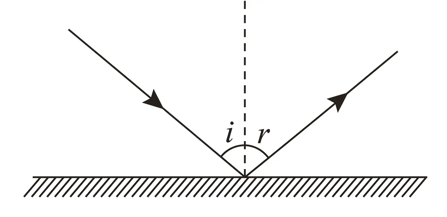
Laws of Reflection
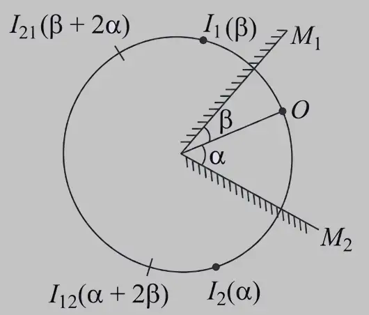
Images in Two Inclined Plane Mirrors
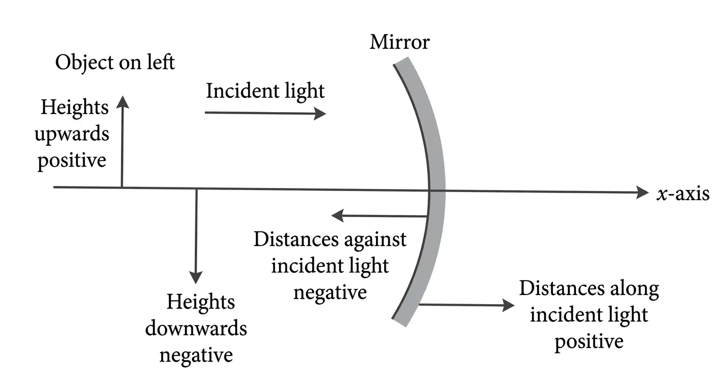
Spherical Mirrors and Sign Convention
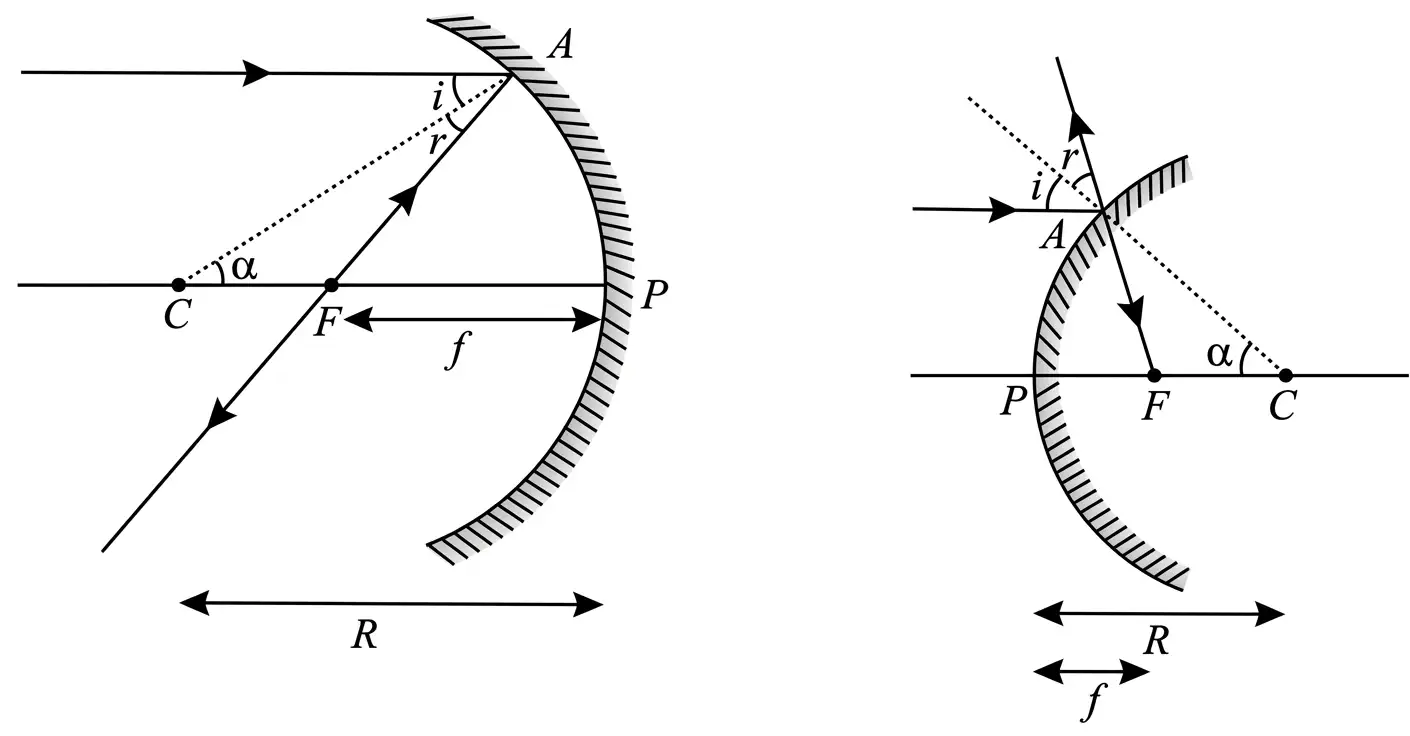
Radius of Curvature and Focal Length
For spherical mirrors and paraxial rays.
Mirror Formula and Lateral Magnification
Use with signed values of , and .
Equivalent forms for spherical mirrors.
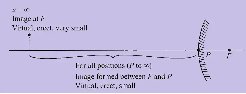
Image Formation by Spherical Mirrors
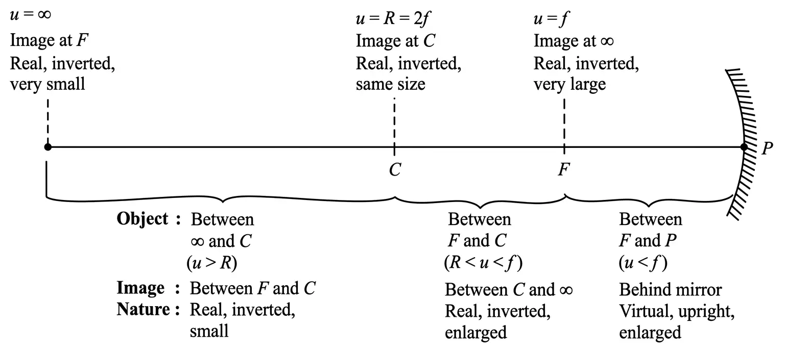
| Object position | Image position and characteristics |
|---|---|
| At infinity | At focus behind mirror; virtual, upright, highly diminished |
| At a finite distance | Between pole and focus behind mirror; virtual, upright, diminished |
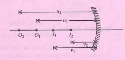
Longitudinal Magnification
Use the magnitudes of the image and object axial lengths.
Using the mirror formula, the signed ratio is related to lateral magnification by .
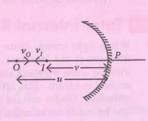
Velocity of an Image
For motion along the principal axis.
State the two laws of reflection.
Write the mirror formula and the lateral magnification relation.
Quick recap
- Light has a wavelength range of about to and travels at about in vacuum.
- The angle of incidence equals the angle of reflection; the incident ray, reflected ray and normal lie in one plane.
- For two mirrors, use and apply the stated integer cases; for non-integer , count the images.
- Concave mirrors reflect from the inner surface; convex mirrors reflect from the outer surface.
- For paraxial rays, ; use and .
- Concave mirrors can form real or virtual images; convex mirrors form virtual, upright, diminished images.
- Longitudinal magnification is for a finite object and for a very small object; it also gives the axial image-velocity ratio.
Refraction
Meaning and bending of light
- Refraction: The change in direction of light as it passes from one medium into another is called refraction.
- Bending: Light bends towards the normal when it enters an optically denser medium and away from the normal when it enters a rarer medium.
Laws of refraction
For light going from medium 1 to medium 2, the relative refractive index of medium 2 with respect to medium 1 is .
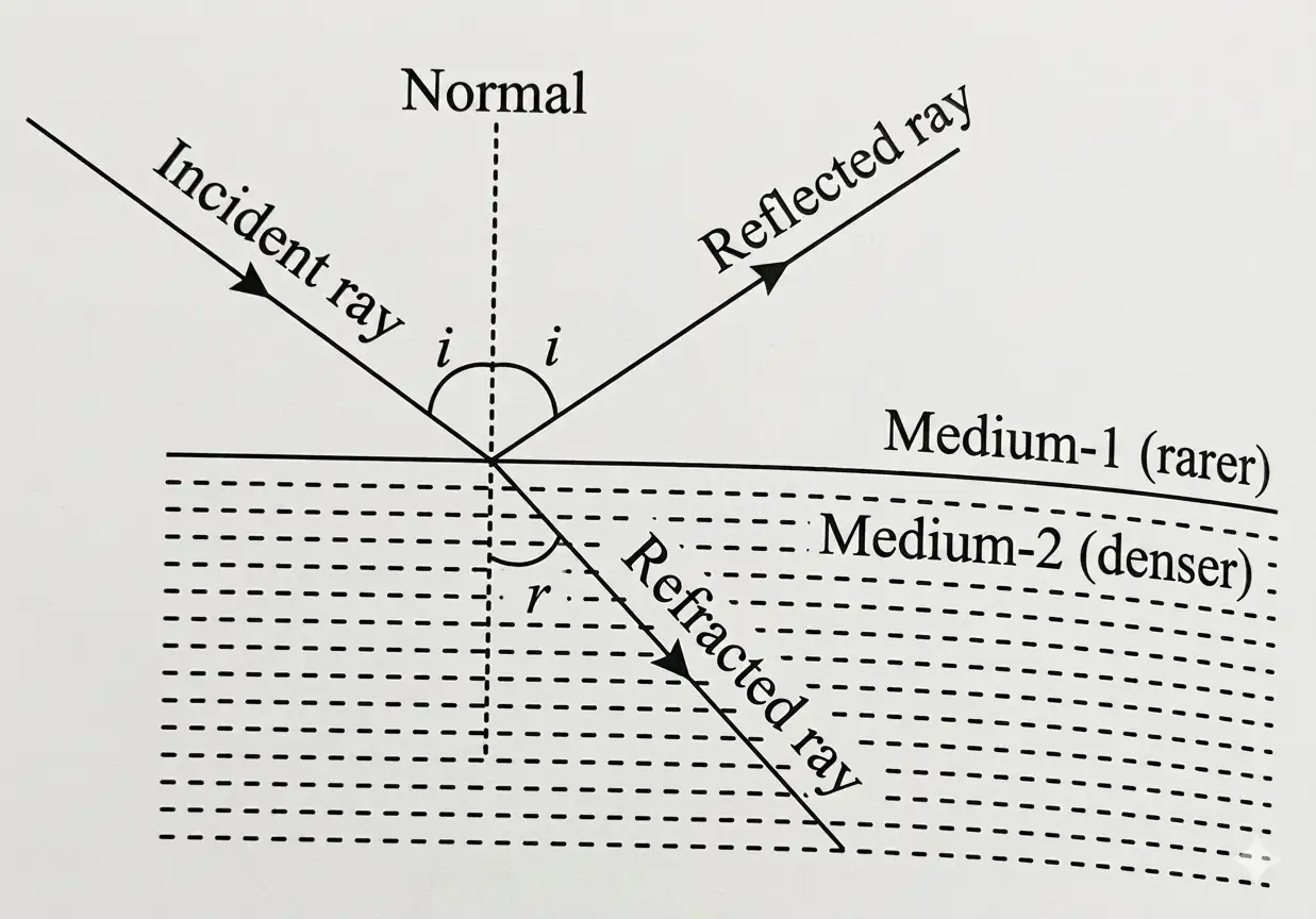
Refractive index and wave quantities
For light passing from medium 1 to medium 2.
At a boundary, frequency remains unchanged; as refractive index increases, speed and wavelength decrease.
Refraction through a glass slab
is the slab thickness; and are the angles of incidence and refraction.
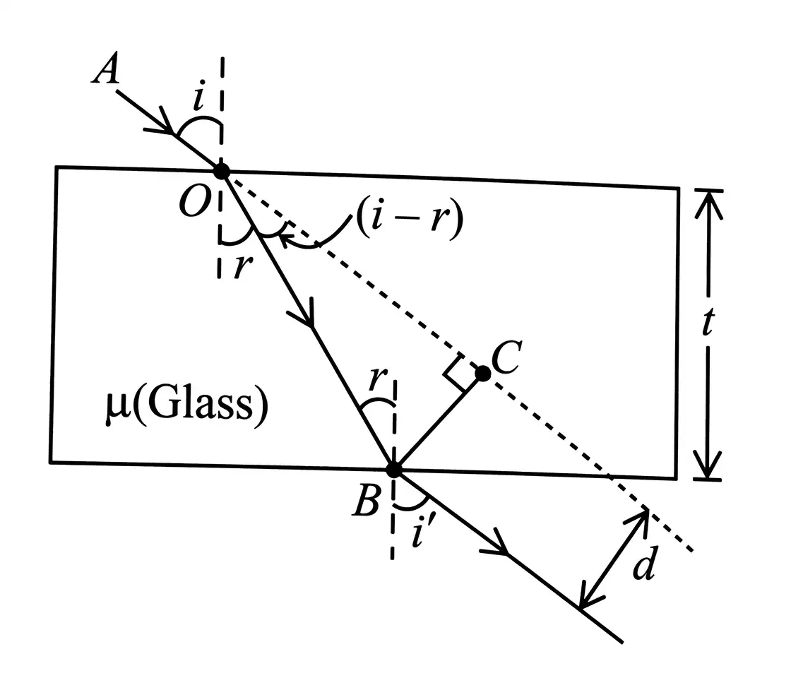
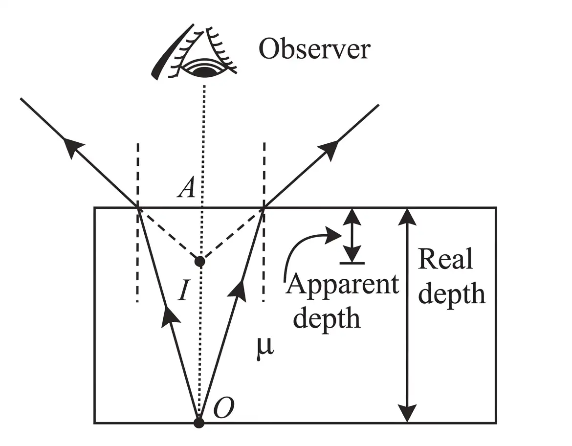
Apparent depth
is the real depth, is the apparent depth and is the refractive index.
For a slab of thickness and refractive index .
For plane-parallel layers, add each layer’s thickness divided by its refractive index.
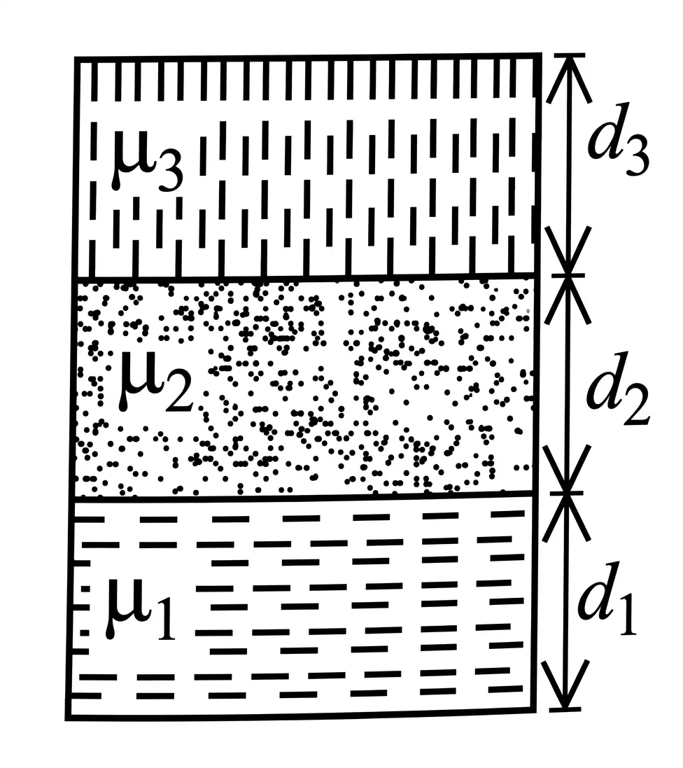
Quick recap
- Refraction: Light bends towards the normal entering a denser medium and away from it entering a rarer medium.
- Snell’s law: .
- Refractive index: ; for two media, .
- Glass slab: Lateral displacement is .
- Apparent depth: Apparent depth real depth divided by refractive index.
- Layered media: Total apparent depth is the sum of for each layer.
Total Internal Reflection
Internal reflection — When light travels from a denser to a rarer medium, part is reflected back into the denser medium and part is refracted into the rarer medium.
Total Internal Reflection
Critical angle and conditions
- Total internal reflection (TIR): Complete reflection back into the denser medium under suitable conditions.
- Critical angle: The incidence angle in the denser medium for which the refracted ray makes an angle of with the normal.
- Direction condition: Light must travel from a denser to a rarer medium, so .
- Angle condition: TIR occurs when ; at , the refracted ray travels along the interface.
From Snell’s law, for light passing from refractive index to .
Optical Fibre
- Construction: A very fine glass or quartz fibre has refractive index about and a lower-index coating of about .
- Working: Light entering at a suitable angle is refracted into the fibre and guided by repeated TIR at the fibre–coating boundary.
- Thickness: The stated order of fibre thickness is .
Refraction at a Spherical Surface
- Setup: An object in a medium of refractive index forms an image in a medium of refractive index across a spherical boundary.
- Paraxial approximation: For small angles, Snell’s law becomes .
- Ray geometry: With the usual diagram and Cartesian signs, and .
- Small-angle relations: , , and .
is object distance, is image distance, and is the radius of curvature; use Cartesian signs.
Refraction at a Plane Surface
- Plane boundary: Set in the spherical-surface formula.
- Distance relation: ; hence actual distance divided by apparent distance is .
Refraction by a Lens
is the refractive index of the lens material relative to the surrounding medium; and are the signed radii of its surfaces.
Use with the Cartesian sign convention for object and image distances.
The signed magnification is the ratio of image height to object height; distances follow the Cartesian sign convention.
Power of a lens — Power measures how strongly a lens converges or diverges incident light; its SI unit is the dioptre ().
Use in metres to obtain power in dioptres; this lens-maker form applies to lenses of any shape.
Combination of Thin Lenses
- In contact: The equivalent power is the sum of the individual powers; this applies to any number of lenses.
- Separated lenses: For two coaxial lenses, their separation changes the equivalent focal length and power.
- Magnification: The total magnification is the product of individual lens magnifications: .
- Uses: Combinations can provide desired convergence or divergence and magnification, improve image sharpness, and are used in cameras, microscopes, telescopes, and other optical instruments.
and are the individual focal lengths; is the equivalent focal length.
is the separation between the thin lenses.
| Property | Combination |
|---|---|
| Focal lengths | and |
| Equivalent focal length | |
| Equivalent power | |
| Behaviour | Acts like a plane glass plate |
Plano-Convex Lens with a Silvered Surface
- Repeated passage: Light passes through the lens, reflects at the silvered surface, then passes through the lens again; the lens power contributes twice.
- Plane mirror: Its focal length is infinite, so it adds no mirror power.
is the lens focal length; is the mirror focal length, with for a plane mirror.
The curved mirror has focal-length magnitude .
State the conditions for total internal reflection and give the critical-angle relation.
Quick recap
- TIR occurs only for light traveling from a denser to a rarer medium with incidence angle greater than the critical angle.
- The critical angle satisfies .
- Optical fibres guide light by repeated TIR between a high-index fibre and lower-index coating.
- Spherical-surface refraction follows ; for a plane surface, actual/apparent distance is .
- Thin lenses obey the lens-maker and thin-lens formulas; lens power is in metre-based units.
- Powers add for thin lenses in contact, while a separated pair uses the separation correction; combined magnification is the product of individual magnifications.
- For a plano-convex lens silvered on a plane or curved surface, or , respectively.
Refraction Through a Prism
Prism and Angle of Deviation
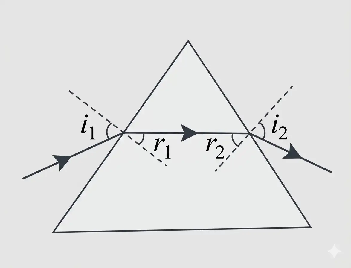
Prism — A homogeneous, transparent medium bounded by two plane refracting surfaces inclined at an angle.
- Refracting angle (): The angle between the two refracting surfaces.
- Deviation (): The angle between the incident ray’s original direction and the emergent ray.
- Internal angles: The refracted angles inside the prism satisfy .
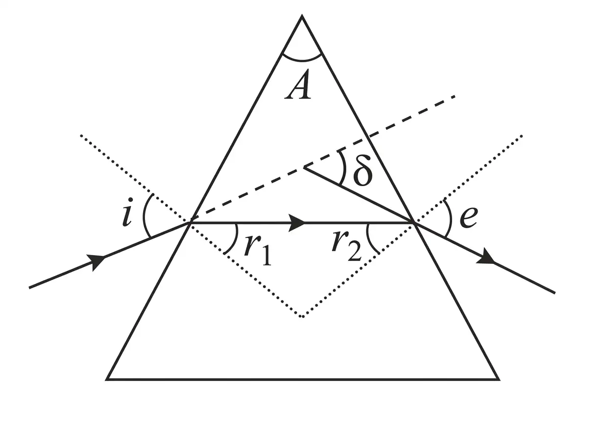
The total deviation equals the sum of the incidence and emergence angles minus the prism angle.
Minimum Deviation
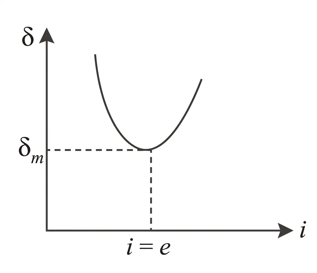
- Variation: As incidence angle increases, deviation first decreases, reaches a minimum , and then increases.
- At minimum deviation: The path is symmetric: and .
- Ray path: Inside the prism, the refracted ray travels parallel to the base.
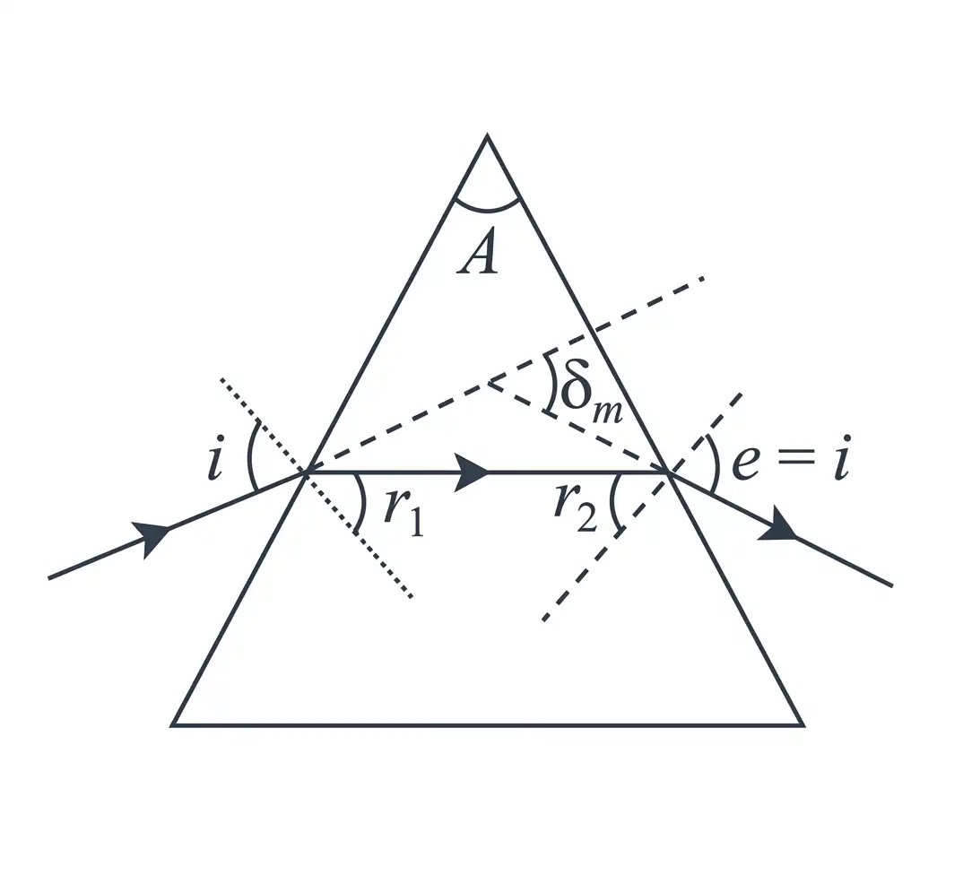
Using and , the prism relations give the incidence and internal refraction angles.
For prism material of refractive index relative to air, use this relation at minimum deviation. For an equiangular prism, .
Thin Prism
Thin prism — A prism with a small refracting angle, for which the deviation is also small.
For small angles, the thin-prism deviation is proportional to the prism angle.
Prism Combinations: Dispersion Without Deviation
- Arrangement: Combine two prisms with their refracting angles oppositely oriented; let their angles be and dispersive powers be .
- No net deviation: The signed deviations cancel, while angular dispersion can remain.
Using the thin-prism relation, the signed deviations must sum to zero.
This signed angle satisfies the no-deviation condition.
With no net deviation, the combination may still disperse colours; and denote violet and red.
Prism Combinations: Deviation Without Dispersion
- No net dispersion: The colour-dependent angular dispersions of the two prisms cancel.
- Net deviation: Even when dispersion cancels, the combination can still deviate the beam.
Use violet and red refractive indices for each prism.
This signed angle makes the net angular dispersion zero.
No dispersion does not necessarily mean no deviation.
| Condition | Dispersion without deviation | Deviation without dispersion |
|---|---|---|
| Cancelled | Net deviation | Net angular dispersion |
| Can remain | Angular dispersion | Deviation |
Condition for No Emergence
- Total internal reflection: At the emergence face, light does not emerge when .
- For all incident rays: The smallest possible must still exceed the critical angle.
- Largest first-face refraction: From Snell’s law, , attained when incidence at the first face is .
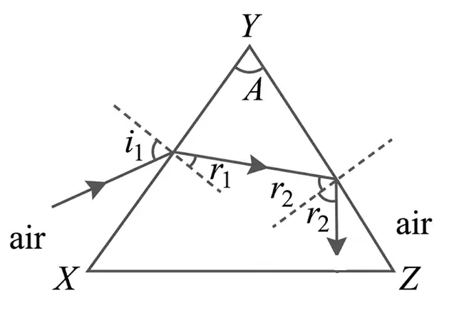
Since , the minimum second-face angle is ; it must be greater than .
Condition for Guaranteed Emergence
- Requirement: For every ray to emerge, the largest possible must be no greater than .
- Extreme case: The smallest first-face refraction angle is , when the incidence angle is zero; therefore .
The limiting ray may emerge at the critical angle; hence equality is allowed.
Write the refractive-index formula for a prism at minimum deviation.
State the thin-prism deviation formula.
Give the conditions for no emergence and guaranteed emergence for all rays.
Quick recap
- Prism deviation is , with .
- At minimum deviation, , , and the internal ray is parallel to the base.
- At minimum deviation, .
- For a thin prism, .
- No deviation and no dispersion are different conditions for combining prisms.
- All rays undergo total internal reflection if ; all rays are guaranteed to emerge if .
Optical Instruments
Simple Microscope
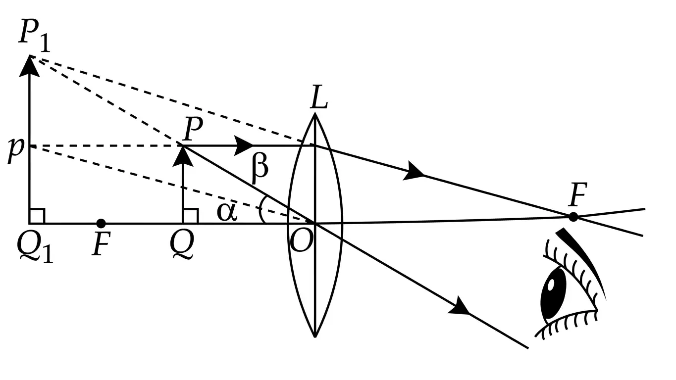
The angular magnifying power is defined when both the object and image are at the least distance of distinct vision, .
| Final image position | Magnifying power |
|---|---|
| At infinity (far point) | |
| At the near point, distance |
Compound Microscope
| Final image position | Magnifying power | Tube length |
|---|---|---|
| At infinity (normal adjustment) | ||
| At the near point, distance |
Astronomical Telescope (Refracting Type)
| Final image position | Magnifying power | Tube length |
|---|---|---|
| At infinity (normal adjustment) | ||
| At the near point, distance |
Terrestrial Telescope
The tube length includes the separation needed for the erecting lens.
Reflecting Telescope
The magnifying power uses the focal length of the mirror objective and the eyepiece.
Cassegrain Telescope
- Primary mirror: A concave mirror reflects incoming light back towards a small convex mirror.
- Secondary mirror: The convex mirror redirects the reflected light through a hole at the centre of the concave mirror.
- Eyepiece: The eyepiece is placed behind the concave mirror, where the light passing through its central hole reaches it.
Quick recap
- A simple microscope uses one converging lens and forms an enlarged, virtual, erect image.
- For a simple microscope, at infinity and at the near point.
- A compound microscope combines objective and eyepiece magnifications; its tube length depends on the final-image position.
- An astronomical telescope has a long-focus, large-aperture objective and a short-focus, small-aperture eyepiece.
- A terrestrial telescope uses an inverting convex erecting lens; a reflecting telescope uses a concave mirror and avoids chromatic aberration.
- A Cassegrain telescope directs reflected light through a central hole to an eyepiece behind its primary mirror.
NEET Physics — ALL CHAPTERS
1
Basic Mathematics
2
Units and Measurement
3
Motion in a Straight Line
4
Motion in a Plane
5
Laws of Motion
6
Work, Energy and Power
7
System of Particles and Rotational Motion
8
Gravitation
9
Mechanical Properties of Solids
10
Mechanical Properties of Fluids
11
Thermal Properties of Matter
12
Thermodynamics
13
Kinetic Theory
14
Oscillations
15
Waves
16
Electric Charges and Fields
17
Electrostatic Potential and Capacitance
18
Current Electricity
19
Moving Charges and Magnetism
20
Magnetism and Matter
21
Electromagnetic Induction
22
Alternating Current
23
Electromagnetic Waves
24
Ray Optics and Optical Instruments
25
Wave Optics
26
Dual Nature of Radiation and Matter
27
Atoms
28
Nuclei
29
Semiconductor Electronics: Materials, Devices and Simple Circuits