NEET UG . NEET Physics . Physics . Wave Optics
Chapter 25: Wave Optics
Ch 25
NEET Physics
NEET UG
Huygens Principle
Wave and Corpuscular Models of Light
Development of the Wave Model
- Corpuscular model: Descartes proposed it in 1637; it is often linked to Newton because of the popularity of his book *Opticks*.
- Corpuscular prediction: If light bends towards the normal on refraction, its speed would be greater in the second medium.
- Wave model: Christian Huygens introduced light’s wave nature in 1678; it explained reflection and refraction.
- Wave prediction: Bending towards the normal on refraction means light travels more slowly in the second medium, contrary to the corpuscular prediction.
- Experimental support: In 1850, Foucault showed that light travels more slowly in water than in air.
- Interference: Thomas Young’s 1801 experiment established the wave nature of light; later interference and diffraction experiments also supported it.
| Model | Speed when light bends towards the normal |
|---|---|
| Corpuscular | Greater in the second medium |
| Wave | Less in the second medium |
Geometrical and Electromagnetic Optics
- Visible-light scale: Wavelengths are very small compared with typical mirrors and lenses; red light has wavelength about .
- Geometrical optics: Treats light as travelling in straight lines by neglecting its finite wavelength.
- Ray: The path of energy propagation in the limit as wavelength tends to zero.
- Maxwell’s explanation: Electromagnetic waves can propagate through vacuum; changing electric and magnetic fields continually produce one another.
- Light: Maxwell identified it as an electromagnetic wave because the calculated speed of electromagnetic waves in free space was close to the measured speed of light.
- Polarisation: Its occurrence shows that light waves are transverse electromagnetic waves.
Wavefronts
Wavefront — The continuous locus of points vibrating in the same phase at a given instant.
- Phase speed: The speed at which a wavefront moves outwards from its source.
- Orientation: A wavefront is always perpendicular to the direction of propagation and therefore to the light rays.
- Example: Each circular ripple produced by a stone in still water forms a wavefront.
| Type | Source or situation | Shape |
|---|---|---|
| Spherical | Point source | Points equidistant from the source lie on a sphere |
| Cylindrical | Linear source, such as a fine slit | Points equidistant from the source lie on a cylinder |
| Plane | Small region of a spherical or cylindrical wavefront far from the source | Approximately flat surface |
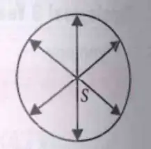
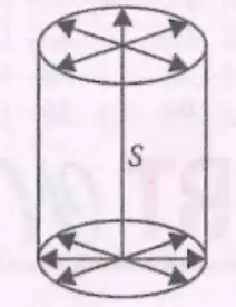
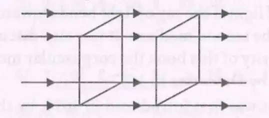
Huygens’ Principle
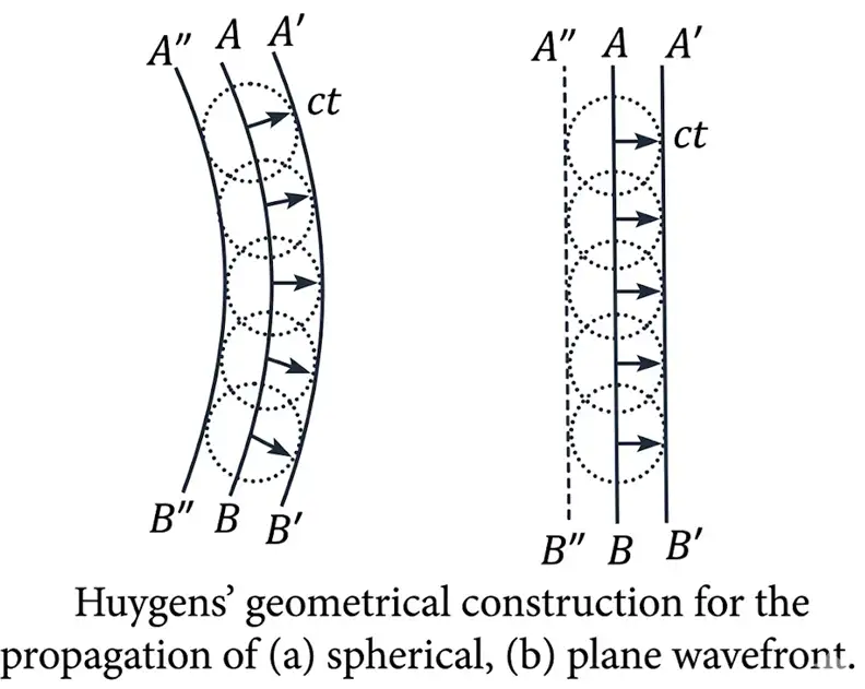
Huygens’ Principle — Every point on a primary wavefront acts as a source of secondary wavelets; the forward envelope of these wavelets forms the new wavefront.
Properties of Secondary Wavelets
- Sources: Every point on the existing wavefront produces a secondary disturbance.
- Propagation: Wavelets spread in all directions at the speed of light in that medium.
- New wavefront: At a later instant, the forward common envelope tangent to the wavelets gives the new wavefront.
- Wave properties: Secondary wavelets have the same frequency and wavelength as the original wave, but reduced intensity.
- Backward direction: Huygens argued that wavelet amplitude is maximum forwards and zero backwards, explaining the absence of a backward wavefront.
After time , each wavelet has travelled a distance equal to the medium’s wave speed multiplied by time.
State Huygens’ principle.
How does the wave model predict the speed of light changes when light bends towards the normal?
Quick recap
- The wave model predicts lower light speed in a medium where refraction bends light towards the normal; Foucault’s 1850 result supported this.
- Young’s 1801 interference experiment supported the wave nature of light.
- Geometrical optics treats light as rays when its wavelength is neglected; light is an electromagnetic transverse wave.
- A wavefront joins points in the same phase and is perpendicular to the direction of propagation.
- Point, linear and distant sources correspond to spherical, cylindrical and approximately plane wavefronts.
- Huygens’ principle constructs each later wavefront as the forward envelope of secondary wavelets.
Refraction and Reflection of Plane Waves Using Huygens Principle
Refraction of a Plane Wave
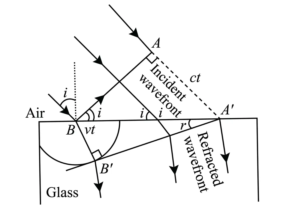
The geometry gives the ratio of the sines of incidence and refraction; and are the wave speeds in air and the denser medium.
Laws of refraction
- First law: The ratio is constant for a given pair of media and equals the relative refractive index .
- Second law: The incident ray, refracted ray and the normal at the point of incidence lie in the same plane.
Reflection of a Plane Wave
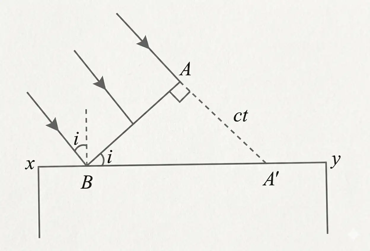
Proof of the law of reflection
- Construction lengths: ; is common, and both triangles have right angles.
- Congruence: The corresponding triangles are congruent, so their corresponding angles are equal: .
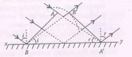
Laws of reflection
- First law: The angle of incidence equals the angle of reflection: .
- Second law: The incident ray, reflected ray and the normal at the point of incidence lie in the same plane.
Measure angles of incidence and refraction from the normal to the surface, not from the surface itself.
How does Huygens’ principle give Snell’s law for refraction?
State the two laws of reflection.
Quick recap
- Huygens’ principle constructs a later wavefront as the common tangent to secondary wavelets.
- For refraction, wavelet speeds are in air and in the denser medium.
- The refraction construction gives .
- For reflection, wavelets travel distance in time .
- The reflection construction proves by triangle congruence.
- For both reflection and refraction, the rays and the normal lie in one plane.
Coherent and Incoherent Addition of Waves
Superposition and Coherence
- Superposition: The resultant displacement at a point is the vector sum of the displacements due to all waves.
- Coherence: Coherent sources maintain a constant phase difference, allowing a sustained interference pattern.
Path Difference and Interference Conditions
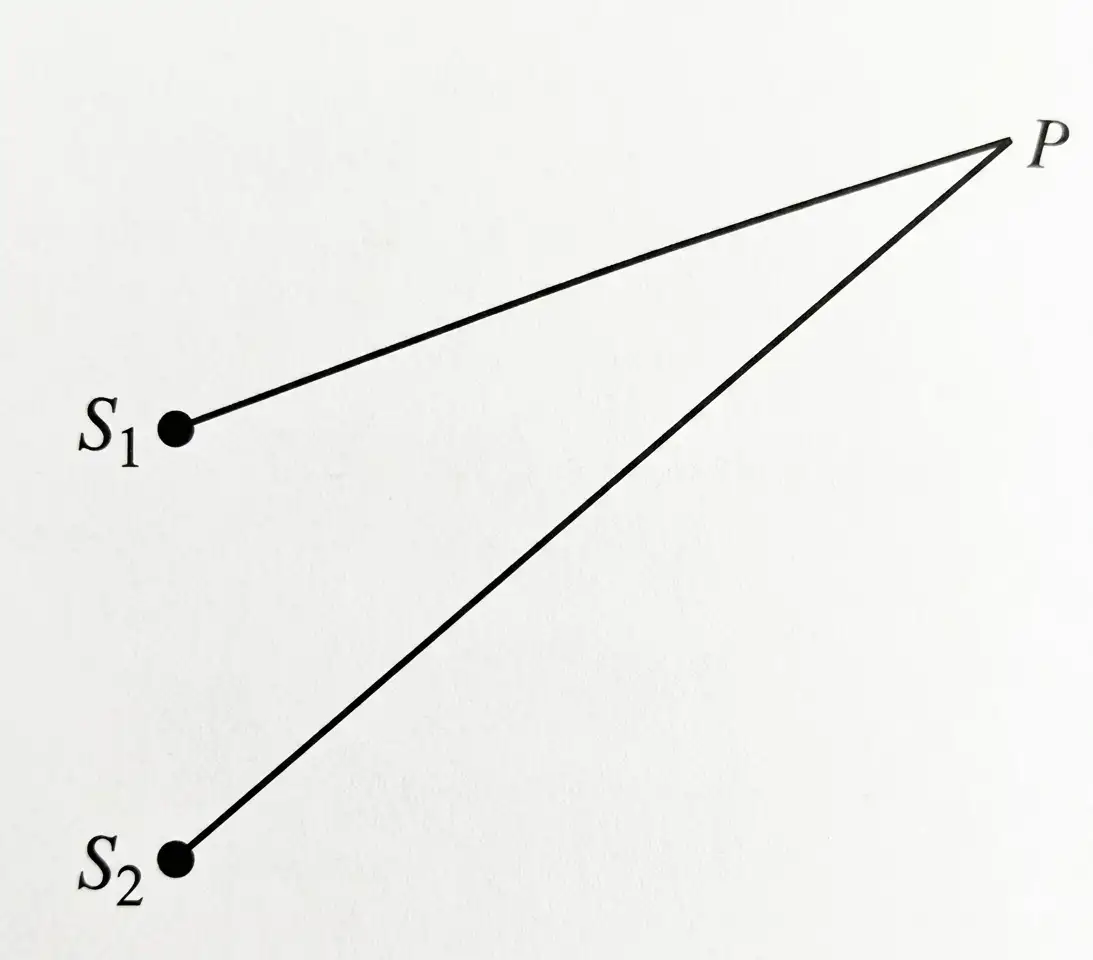
Resultant Displacement and Intensity for Equal Amplitudes
For and , add the displacements to obtain the resultant.
The maximum occurs for ; the minimum occurs for .
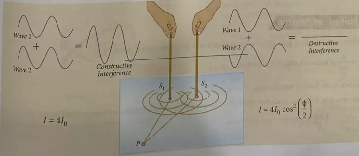
Coherent Waves with Unequal Amplitudes
Here, and are the individual amplitudes and is the phase difference.
Here, and are the intensities of the individual waves.
Use this ratio to compare the brightest and darkest points of an interference pattern.
Intensity and Slit Width
Here, and are the slit widths and and are the corresponding amplitudes.
Incoherent Addition and Maxima Loci
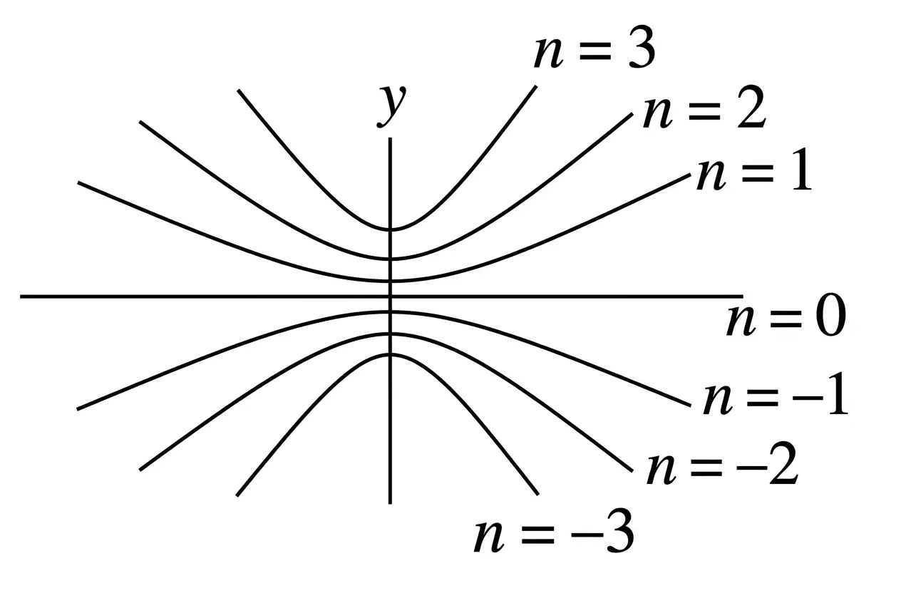
What conditions give constructive and destructive interference?
How do intensities add for coherent and incoherent waves?
Quick recap
- Interference results from superposition; a stable pattern requires a constant phase difference.
- Constructive interference occurs for and destructive interference for .
- For equal amplitudes, .
- For unequal coherent waves, intensity includes the phase-dependent term .
- For incoherent waves, the individual intensities add directly.
- Light intensity is proportional to slit width and to the square of wave amplitude.
Interference of Light Waves and Young’s Experiment
Superposition and Coherent Sources
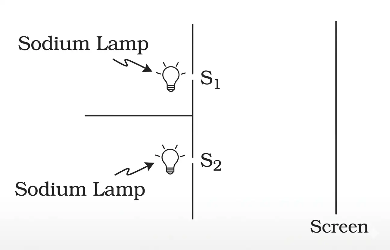
Young’s Double-Slit Experiment
Arrangement and Path Difference
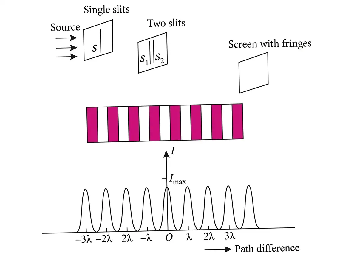
- Coherent slits and are illuminated from a common source, locking the phase relation between the waves.
- Geometry: slit separation is , screen distance is , and point is displaced by from the central point.
- For and small angles, the path difference at is approximately .
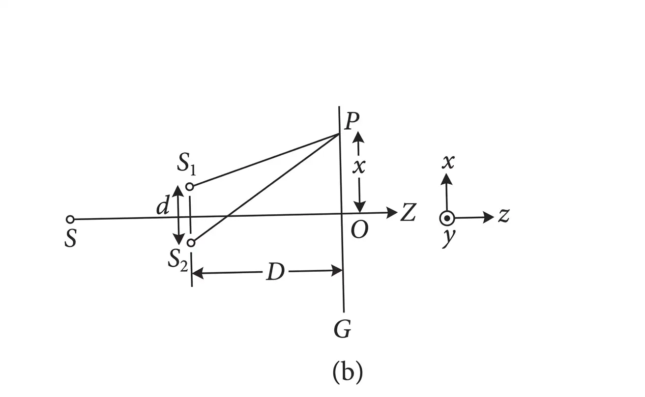
| Fringe | Condition | Position |
|---|---|---|
| Bright (constructive) | ||
| Dark (destructive) |
Fringe Pattern
- Order: ; the bright fringe at is the central maximum.
- Central fringe: at , , so the path difference is zero and the fringe is bright.
- Fringe width: the distance between successive bright fringes, or successive dark fringes, is ; bright and dark fringes are equally spaced.
- Shape: exact loci of constant path difference are hyperbolas; when is large compared with the fringe width, the fringes are nearly straight lines.
- Central line: points along the line through perpendicular to the plane of the diagram are equidistant from both slits, forming a straight bright fringe.
Displacement of Fringes
Transparent Sheet in One Path
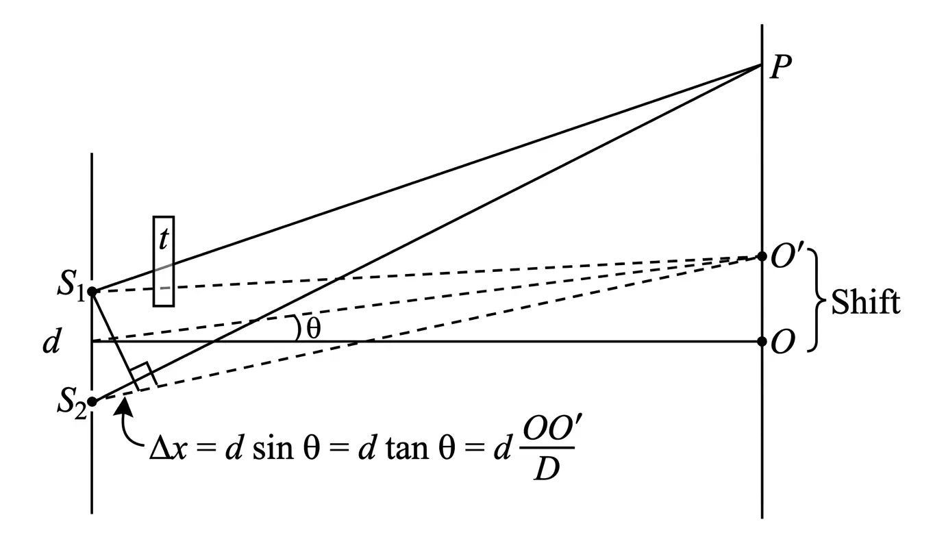
- Extra optical path: inserting a transparent sheet of thickness and refractive index adds a path difference of .
- Fringe shift: the pattern shifts towards the side where the sheet is placed.
- Shifted fringe count: the number of fringe widths shifted is independent of screen distance and slit separation.
Here is the shift of the pattern and is the screen distance.
Use for the fringe width.
Interference in Thin Films
Origin of Colours
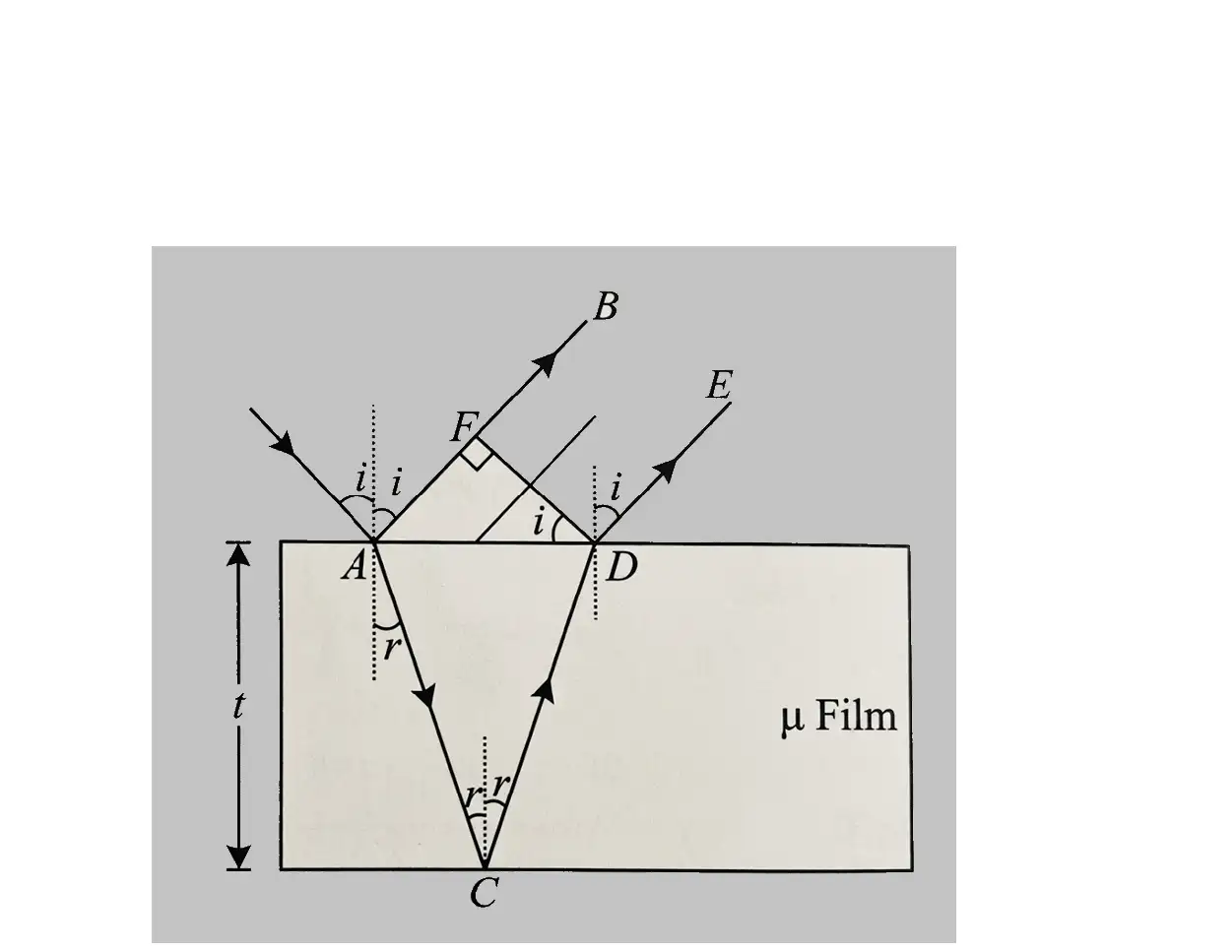
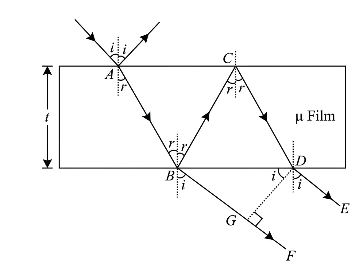
- Thin-film colours in soap films or oil films on water arise from interference between light waves reflected from the film’s surfaces.
- White light contains different wavelengths, and the interference conditions select different wavelengths at different places, producing colour.
| Observed waves | Constructive interference | Destructive interference |
|---|---|---|
| Reflected | ||
| Transmitted |
Normal Incidence
- At normal incidence, , so ; apply this substitution in either reflected- or transmitted-wave condition.
State the conditions for bright and dark fringes in Young’s double-slit experiment.
How many fringes shift when a sheet is inserted in one path?
Give the reflected-light conditions for constructive and destructive interference in a thin film.
Quick recap
- Interference is based on superposition; stable fringes need coherent sources with a constant phase difference.
- In Young’s experiment, ; bright and dark positions follow their respective path-difference conditions.
- The fringe width is , and the central fringe is bright.
- A sheet shifts fringes towards itself by , or fringe widths.
- Thin-film reflected and transmitted conditions for brightness and darkness are complementary.
- At normal incidence, set in the thin-film conditions.
Diffraction
Diffraction — The spreading and bending of waves as they pass through an opening whose size is comparable to their wavelength.
When diffraction is significant
- Dependence: The amount of bending depends on the aperture size relative to the wavelength.
- Strong diffraction: Bending is considerable when the aperture width is comparable to the wavelength.
Single-Slit Diffraction
Huygens' explanation
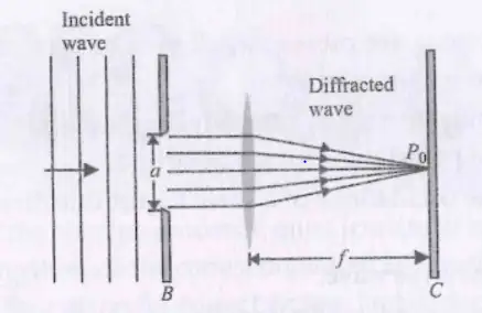
- Slit wavelets: Every point across slit acts as a source of secondary wavelets, starting in the same phase.
- Spread: The wavelets travel in different directions, producing diffraction after passing through the slit.
- Observation: A convex lens can focus the diffraction pattern on a screen in its focal plane.
Diffraction Pattern
Central maximum
- At : Rays arriving at the centre are in phase, so the intensity is maximum.
Minima
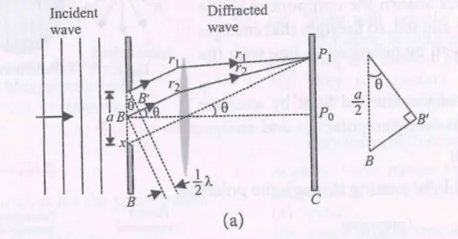
- First minimum: The slit can be paired into halves whose corresponding rays differ in path by ; this gives destructive interference when .
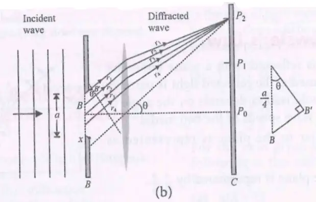
- General condition: Minima occur when the path difference across the slit is an integer multiple of the wavelength.
Here is a non-zero integer.
Secondary maxima
- Position: A secondary maximum lies approximately halfway between each adjacent pair of minima.
The stated positions are approximate.
For small angles, the first minima are at approximately ; the full angular width is the separation between them.
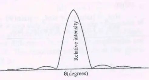
is the central maximum intensity, and is the intensity at angle .
Effect of slit width
- Wider slit: Increasing makes the central diffraction peak narrower.
State the conditions for minima in single-slit diffraction.
Quick recap
- Diffraction is significant when the aperture width is comparable to the wavelength.
- Every point across a slit acts as a coherent source of secondary wavelets.
- The central maximum forms because rays reaching its centre are in phase.
- Single-slit minima satisfy for non-zero integer .
- The central maximum has angular width for small angles.
- A wider slit produces a narrower central diffraction peak.
Polarisation
Polarisation of Light
- Polarisation: The restriction of a transverse wave’s vibrations to one direction perpendicular to its propagation is called polarisation.
- Significance: Polarisation demonstrates that light waves are transverse.
Polarising Sheets (Polaroids)
For incident intensity , the transmitted intensity is half as large.
Malus’ Law
Use this relation to find the intensity transmitted through the analyser.
| Axes | Angle | Transmitted intensity |
|---|---|---|
| Parallel | ||
| Perpendicular | ||
| Inclined |
Polarisation by Reflection and Brewster’s Law

Here, is the refractive index of the second medium relative to the first, is Brewster’s angle, and is the refraction angle.
State Malus’ law and explain its symbols.
State Brewster’s law and the condition at Brewster’s angle.
Quick recap
- Polarisation restricts transverse vibrations to one direction and occurs only for transverse waves.
- One Polaroid converts unpolarised light to plane-polarised light and transmits intensity .
- Malus’ law gives analyser output as ; parallel axes transmit maximum intensity and perpendicular axes transmit zero.
- At Brewster’s angle, reflected light is plane-polarised, refracted light is partially polarised, and the beams are perpendicular.
- Brewster’s law is .
NEET Physics — ALL CHAPTERS
1
Basic Mathematics
2
Units and Measurement
3
Motion in a Straight Line
4
Motion in a Plane
5
Laws of Motion
6
Work, Energy and Power
7
System of Particles and Rotational Motion
8
Gravitation
9
Mechanical Properties of Solids
10
Mechanical Properties of Fluids
11
Thermal Properties of Matter
12
Thermodynamics
13
Kinetic Theory
14
Oscillations
15
Waves
16
Electric Charges and Fields
17
Electrostatic Potential and Capacitance
18
Current Electricity
19
Moving Charges and Magnetism
20
Magnetism and Matter
21
Electromagnetic Induction
22
Alternating Current
23
Electromagnetic Waves
24
Ray Optics and Optical Instruments
25
Wave Optics
26
Dual Nature of Radiation and Matter
27
Atoms
28
Nuclei
29
Semiconductor Electronics: Materials, Devices and Simple Circuits