NEET UG . NEET Physics . Physics . System of Particles and Rotational Motion
Chapter 7: System of Particles and Rotational Motion
Ch 7
NEET Physics
NEET UG
Centre of Mass
Rigid-Body Motion
- Rigid body: An ideal rigid body has a definite, unchanging shape; distances between all pairs of its particles remain constant.
- Translation: In pure translation, every particle of the body has the same velocity at any instant.
- Rotation: About a fixed axis, each particle moves in a circle in a plane perpendicular to the axis; particles on the axis remain stationary.
- Combined motion: A free rigid body may undergo both translation and rotation, so its particles can have different velocities.
- Precession: The axis of a spinning top may move around the vertical, sweeping out a cone.
Motion of Centre of Mass
Position of the Centre of Mass
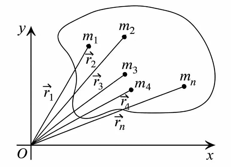
Centre of mass (COM) — The centre of mass is the position representing the mass-weighted average location of all particles in a system.
- Total mass: For particles of masses , the system’s total mass is .
- Position vectors: If each particle is at , the COM position vector is , measured from the same origin.
Use this vector relation for a system of particles.
Velocity and Acceleration of the Centre of Mass
- Velocity: Differentiating the COM position relation with respect to time gives the mass-weighted average velocity.
- Acceleration: Differentiating the velocity relation gives the mass-weighted average acceleration.
.
.
External Force and COM Motion
- Newton’s second law: The total force on the system equals the rate of change of its total momentum.
- Internal forces: Pairwise internal forces cancel in the system’s total-force equation; they do not determine the COM’s motion.
- External forces: Only the net external force changes the motion of the COM.
The system moves as if its total mass were concentrated at the COM and the net external force acted there.
Projectile Explosion
- Trajectory: If a projectile explodes during flight, its fragments’ COM continues along the same parabolic path the projectile would have followed without the explosion.
- Reason: The explosion creates internal forces between fragments, which do not change the COM motion; the external force remains unchanged.
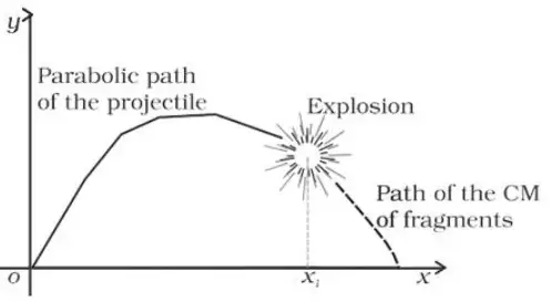
Do not confuse individual particle motion with COM motion: internal forces can alter each particle’s path, but only the net external force governs the COM.
Quick recap
- The COM position is the mass-weighted average of particle positions.
- The COM velocity and acceleration are mass-weighted averages of particle velocities and accelerations.
- Internal forces cancel in the system-level equation of motion.
- The net external force determines COM acceleration: .
- An exploded projectile’s fragments’ COM follows the original projectile trajectory.
Linear Momentum of a System of Particles
Total Momentum and Centre of Mass
Linear momentum of a system — The total momentum of a system is the vector sum of the momenta of all its particles.
For particles of masses and velocities , the total mass is and the centre-of-mass velocity is .
External Force and Momentum Conservation
Newton’s second law for a system
- Net external force determines the rate of change of the system’s total momentum: .
- Centre-of-mass motion follows the same force relation: the system’s centre of mass accelerates in the direction of the net external force.
When the net external force is zero, total momentum remains constant and the centre of mass moves with constant velocity.
Nuclear splitting example
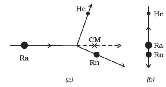
- Radium splitting: A heavy radium nucleus splits into a radon nucleus and an alpha particle (helium nucleus).
- If the centre of mass is already moving: With no net external force, it continues in uniform motion.
- If the centre of mass is at rest: The radon and alpha particle fly apart in opposite directions; their momenta are equal and opposite, so total momentum remains zero.
State the condition for conservation of the total linear momentum of a system.
Quick recap
- Total system momentum is the vector sum of the momenta of its particles.
- The relation between system momentum and centre-of-mass velocity is .
- The rate of change of total momentum equals the net external force.
- Zero net external force means constant total momentum and constant centre-of-mass velocity.
- When a system initially at rest splits, the products’ momenta are equal and opposite.
Vector Product of Two Vectors
Definition and Magnitude
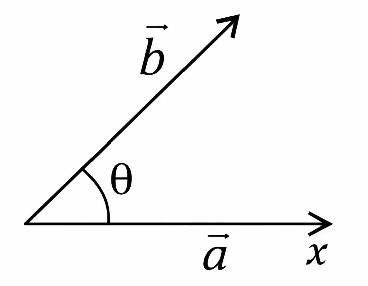
Direction and Unit-Vector Products
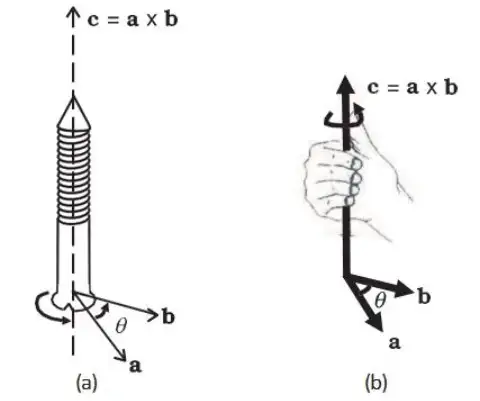
Right-hand rule
- Rule: Curl the fingers of your right hand from toward ; your thumb gives the direction of .
- Direction: The result is normal to the plane of the two vectors.
| Order | Products |
|---|---|
| Cyclic | ; ; |
| Anticyclic | ; ; |
| Same unit vector |
Do not reverse the order without changing the sign: .
Component Form
- Components: Write and .
- Method: Expand using distributivity and the unit-vector products; collect the coefficients of , , and .
Use this expression to calculate the vector product from Cartesian components.
Quick recap
- The cross product has magnitude and points perpendicular to both vectors.
- Use the right-hand rule to determine its direction.
- Cyclic unit-vector products are positive; reversing the order gives the negative result.
- The cross product of a unit vector with itself is zero.
- Use the component formula to calculate from Cartesian components.
Angular Velocity and its Relation With Linear Velocity
Angular Velocity in Rotational Motion
- Angular velocity: In pure rotation, all parts of a rigid body have the same angular velocity at any instant.
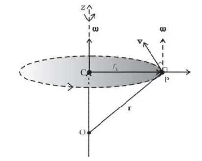
- Direction: For rotation about a fixed axis, the angular velocity vector lies along the axis and follows the right-hand screw rule.
- Linear velocity: A point with position vector has velocity .
- Angular acceleration: It is the time rate of change of angular velocity, .
Quick recap
- In pure rotation, all parts of the body have the same angular velocity at any instant.
- For rotation about a fixed axis, the angular velocity vector lies along the axis.
- The right-handed screw rule determines the direction of the angular velocity vector.
- Linear velocity is given by .
- Angular acceleration is the time rate of change of angular velocity: .
Torque and Angular Momentum
Torque (Moment of Force)
Here is the angle between and ; is the perpendicular moment arm.
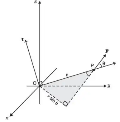
When torque is zero
- Zero torque: if , , or or .
- Reason: Torque vanishes when the force's line of action passes through the reference point, so the perpendicular moment arm is zero.
Angular Momentum of a Particle
Here is the angle between and .
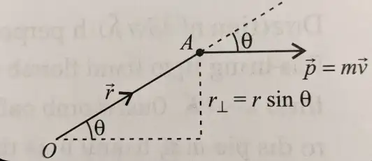
Torque and the Rate of Change of Angular Momentum
Angular Momentum of a System of Particles
Each is measured from the same reference point.
Conservation of angular momentum
- If the net external torque is zero, .
- Then .
- Therefore the system's total angular momentum remains constant: .
State the relation between torque and angular momentum.
When is the angular momentum of a system conserved?
Quick recap
- Torque is ; its magnitude is force times perpendicular moment arm.
- Angular momentum of a particle is .
- For a particle, .
- System angular momentum is the vector sum of the angular momenta of its particles.
- Internal torques cancel in pairs, leaving the external torque as the system's net torque.
- Zero net external torque implies conservation of total angular momentum.
Equilibrium of a Rigid Body
Translational Equilibrium
The net external force is zero, so momentum is constant.
Rotational Equilibrium
The net torque is zero, so angular momentum is constant.
Principle of Moments and the Lever
For translational equilibrium, the normal reaction equals the sum of the applied forces.
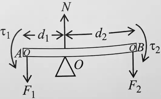
Lever torque balance
- Rotational equilibrium: The opposing torques about the pivot are equal.
- Lever arms: Each arm is the perpendicular distance from the pivot to the force’s line of action.
- Load and effort: The product of each force and its lever arm gives the corresponding torque.
Here, F₁ is the load and F₂ is the effort.
A lever has mechanical advantage greater than one when the effort arm is longer than the load arm; then a small effort can lift a heavy load.
Do not confuse the load arm with the effort arm: in this lever, d₁ is the load arm and d₂ is the effort arm.
Centre of Gravity
- Definition: The centre of gravity is the point at which the whole weight of a body may be considered to act.
- Torque: The total gravitational torque about the centre of gravity is zero.
- Uniform gravity: In a uniform gravitational field, the centre of gravity coincides with the centre of mass.
Quick recap
- Translational equilibrium requires zero net external force; linear momentum is constant.
- Rotational equilibrium requires zero net torque; angular momentum is constant.
- The principle of moments states that the algebraic sum of moments about a fixed point is zero.
- For the ideal lever, force balance gives N = F₁ + F₂ and torque balance gives F₁d₁ = F₂d₂.
- Mechanical advantage is load divided by effort and equals effort arm divided by load arm.
- The centre of gravity is the point of action of weight where total gravitational torque is zero.
Moment of Inertia
Moment of inertia
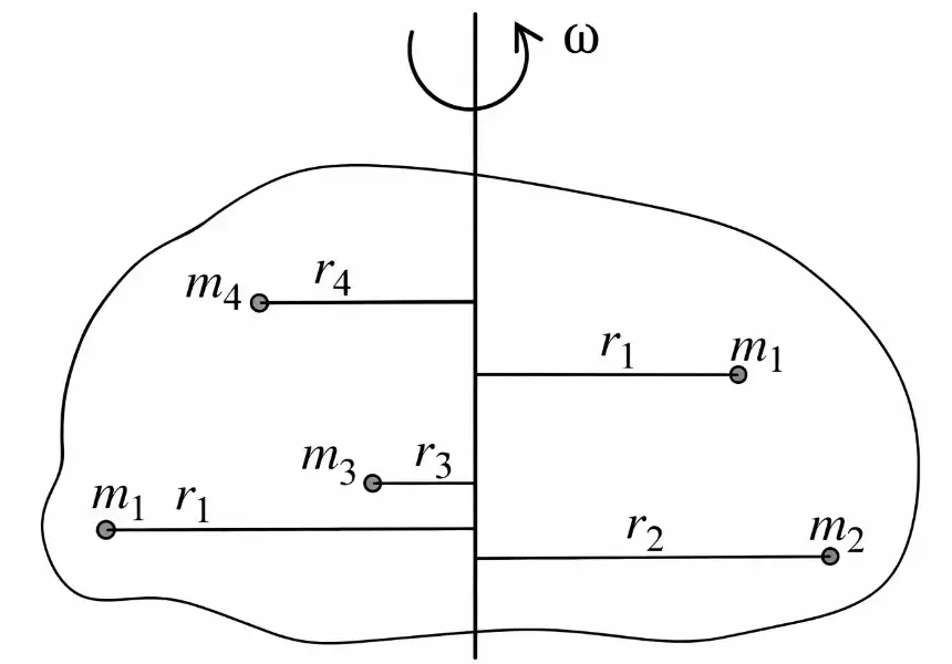
For discrete particles, add each mass multiplied by the square of its distance from the axis. For a continuous body, integrate over its mass elements.
Using , the kinetic energy of a rotating system takes the rotational form shown.
Units
- SI unit: .
- Dimensions: Mass multiplied by length squared.
Radius of gyration
For any mass distribution, use . For equal-mass particles, this becomes the mean-square-distance formula.
Theorems of axes
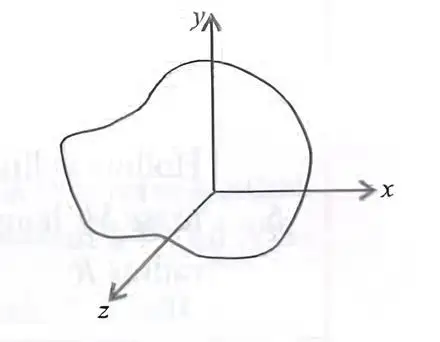
Here, and lie in the plane and is perpendicular to it.
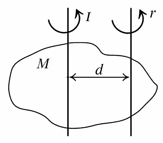
is about the centre-of-mass axis; is about the shifted parallel axis, and is the distance between them.
Moments of inertia of regular bodies
| Body | Axis | Moment of inertia |
|---|---|---|
| Uniform ring, mass , radius | Through centre, perpendicular to plane | |
| Uniform ring, mass , radius | Along a diameter | |
| Uniform ring, mass , radius | Tangent in its plane | |
| Uniform ring, mass , radius | Tangent perpendicular to its plane | |
| Uniform disc, mass , radius | Through centre, perpendicular to plane | |
| Uniform disc, mass , radius | Along a diameter | |
| Uniform disc, mass , radius | Tangent in its plane | |
| Uniform disc, mass , radius | Tangent perpendicular to its plane | |
| Solid sphere, mass , radius | Along a diameter | |
| Solid sphere, mass , radius | Tangential axis | |
| Hollow sphere, mass , radius | Along a diameter | |
| Hollow sphere, mass , radius | Tangential axis | |
| Solid cylinder, mass , length , radius | Along its own axis | |
| Solid cylinder, mass , length , radius | Through centre, perpendicular to its own axis | |
| Solid cylinder, mass , length , radius | Along a diameter of one end face | |
| Hollow cylinder, mass , length , radius | Along its own axis | |
| Hollow cylinder, mass , length , radius | Through centre, perpendicular to its own axis | |
| Thin rod, mass , length | Through centre, perpendicular to rod | |
| Thin rod, mass , length | Through one end, perpendicular to rod | |
| Rectangular lamina, mass , length , breadth | Through centre, perpendicular to plane |
State the perpendicular axes theorem and its condition.
How is the moment of inertia about a shifted parallel axis calculated?
Quick recap
- Moment of inertia measures rotational inertia and depends on mass distribution relative to the axis.
- For particles, ; for continuous bodies, .
- Rotational kinetic energy is ; the SI unit of is .
- Radius of gyration satisfies and .
- For a plane lamina, the perpendicular axes theorem gives .
- For parallel axes, .
- Use the standard-body table with careful attention to the specified axis.
Kinematics of Rotational Motion about a Fixed Axis
Rotational Kinematic Equations
- Angular velocity: For constant angular acceleration, .
- Angular displacement: .
- Velocity-displacement relation: .
- Symbols: and are initial and final angular velocities; is angular acceleration and is time.
Quick recap
- The rotational kinematic equations describe rotation about a fixed axis.
- They apply for constant angular acceleration .
- gives angular velocity after time .
- gives angular displacement.
- relates angular velocity and displacement without time.
Dynamics of Rotational Motion about a Fixed Axis
Torque About a Fixed Axis
Torque component about the axis — Only the torque component along the fixed axis contributes to rotation about that axis.
Which force and position components matter?
- Forces: Consider only force components in planes perpendicular to the axis; forces parallel to the axis produce torque perpendicular to it.
- Position vectors: Use only components perpendicular to the axis; components along the axis produce torque perpendicular to it.
- Result: Torque components perpendicular to the axis do not contribute to rotation about the fixed axis.
Work and Power in Rotational Motion
- Small angular displacement: A particle on the rotating body moves through a small arc while the body turns through .
- Work by torque: The work done by one force is .
- Net work: For several forces, their torques add: .
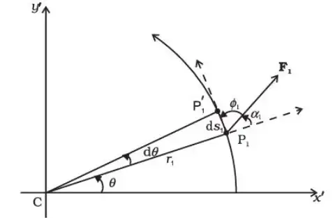
Power is the rate of doing work; use this relation for rotation about a fixed axis.
Torque and Angular Acceleration
- Rotational kinetic energy: For a rigid body with constant moment of inertia, .
- Rate of change: Differentiating with respect to time gives .
- Rotational equation of motion: Equating the power supplied by torque, , to the rate of increase of rotational kinetic energy, , gives .
Linear and Rotational Motion Compared
| Quantity | Linear motion | Rotational motion |
|---|---|---|
| Displacement | Angular displacement | |
| Velocity | Angular velocity | |
| Acceleration | Angular acceleration | |
| Inertia | Mass | Moment of inertia |
| Force / torque law | ||
| Work | ||
| Kinetic energy | ||
| Power | ||
| Momentum | Linear momentum | Angular momentum |
State the rotational equation of motion about a fixed axis.
Write the expressions for work and power in rotational motion.
Quick recap
- For a fixed axis, only torque components along the axis affect the rotation.
- Rotational work for a small angular displacement is .
- Rotational power is .
- Rotational kinetic energy is .
- The rotational equation of motion is .
- Mass corresponds to moment of inertia, and linear momentum corresponds to angular momentum.
Angular Momentum in Case of Rotation about a Fixed Axis
Angular Momentum About a Fixed Axis
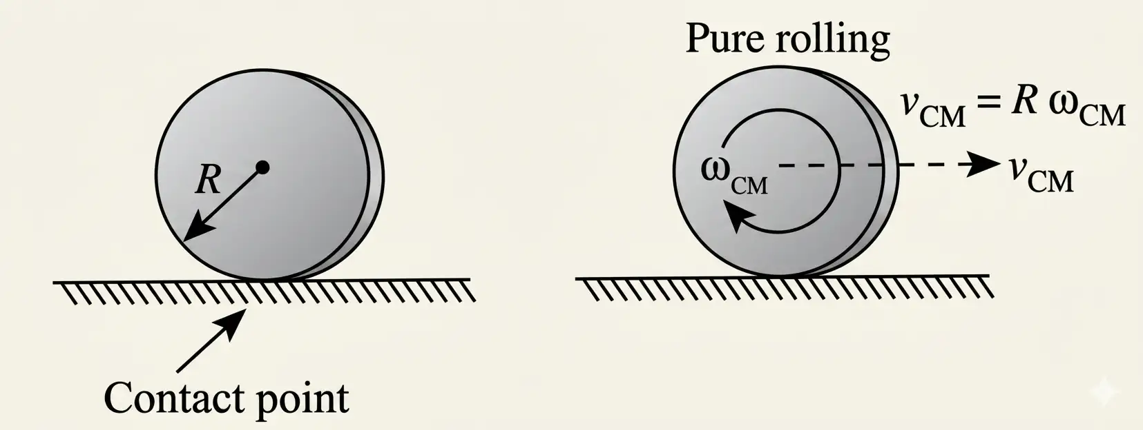
Rolling Motion
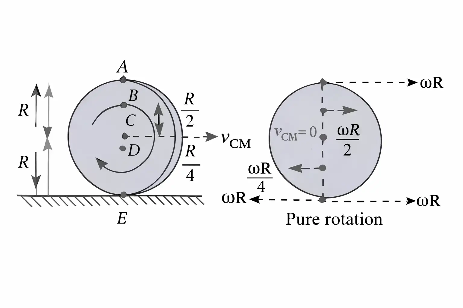
Kinetic Energy of a Rolling Body
- Energy: Rolling motion combines the translational kinetic energy of the centre of mass with rotational kinetic energy about it.
- Total kinetic energy: ; for pure rolling, .
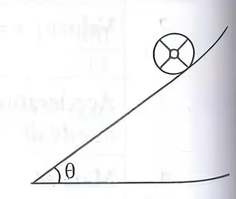
A Spherical Body on a Rough Incline
| Physical quantity | Pure rolling | Pure sliding |
|---|---|---|
| Acceleration | ||
| Speed after descending height | ||
| Time to travel distance |
State the condition for pure rolling and the relation between centre-of-mass speed and angular speed.
Write the total kinetic energy of a body in pure rolling.
What is the minimum coefficient of friction required for pure rolling down an incline?
Quick recap
- For a system, ; for fixed-axis rotation, .
- The axial component is , while and .
- The torque for fixed-axis rotation is .
- Rolling combines translation and rotation; pure rolling requires .
- Rolling kinetic energy includes both translational and rotational parts: .
- Friction must reach for rolling without slipping down an incline.
- For the same incline and height, pure sliding reaches a greater speed than pure rolling.
NEET Physics — ALL CHAPTERS
1
Basic Mathematics
2
Units and Measurement
3
Motion in a Straight Line
4
Motion in a Plane
5
Laws of Motion
6
Work, Energy and Power
7
System of Particles and Rotational Motion
8
Gravitation
9
Mechanical Properties of Solids
10
Mechanical Properties of Fluids
11
Thermal Properties of Matter
12
Thermodynamics
13
Kinetic Theory
14
Oscillations
15
Waves
16
Electric Charges and Fields
17
Electrostatic Potential and Capacitance
18
Current Electricity
19
Moving Charges and Magnetism
20
Magnetism and Matter
21
Electromagnetic Induction
22
Alternating Current
23
Electromagnetic Waves
24
Ray Optics and Optical Instruments
25
Wave Optics
26
Dual Nature of Radiation and Matter
27
Atoms
28
Nuclei
29
Semiconductor Electronics: Materials, Devices and Simple Circuits