NEET UG . NEET Physics . Physics . Electromagnetic Induction
Chapter 21: Electromagnetic Induction
Ch 21
NEET Physics
NEET UG
The Experiments of Faraday and Henry
Electromagnetic Induction
- Electromagnetic induction: An emf is induced when the magnetic flux linked with a circuit changes.
- Induced current: A current flows when the circuit is closed, and persists while the flux is changing.
Experiments of Faraday and Henry
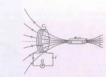
Experiment 1: Magnet and coil
- Motion matters: Pushing a bar magnet towards a coil causes the galvanometer to deflect, indicating current in the coil.
- Transient current: The deflection lasts only while the magnet is moving; when its motion stops, the induced current ceases.
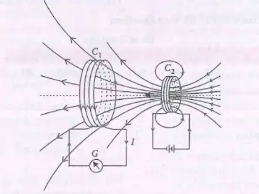
Experiment 2: Motion of a current-carrying coil
- Setup: Coil carries current, while coil is connected to a galvanometer.
- Observation: Moving induces current in , shown by galvanometer deflection.
- Key idea: Relative motion changes the magnetic field experienced by .
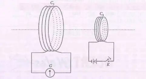
Experiment 3: Switching current in a nearby coil
- Setup: Coil is connected to galvanometer ; coil is connected to a battery through key .
- Closing the key: Pressing produces a momentary galvanometer deflection in ; the pointer soon returns to zero.
- Steady current: Keeping closed causes no continuing deflection in .
- Opening the key: Releasing produces a momentary deflection in the opposite direction.
- Induced current appears when the magnetic field through a coil changes.
- A steady magnetic field produces no induced current; switching or motion produces a transient current.
- Opposite changes—switching on and switching off—produce deflections in opposite directions.
Quick recap
- Faraday and Henry demonstrated that changing magnetic conditions can induce current in a closed coil.
- Moving a magnet towards a coil produces a galvanometer deflection only while it moves.
- Motion of a current-carrying coil can induce current in a nearby coil.
- Switching current in one coil induces a momentary current in a nearby coil.
- A steady current gives no continuing induced current; opening the circuit reverses the deflection.
Magnetic Flux
Magnetic Flux Through a Surface
Magnetic flux — The magnetic flux through a surface measures the magnetic field passing through it; for a uniform field, it is the dot product of the field and area vectors.
Key points
- Area vector has magnitude equal to the surface area and points perpendicular to the surface.
- Angle is measured between the magnetic field and the area vector , not between the field and the surface.
- Orientation Flux is maximum when is parallel to , zero when they are perpendicular, and negative when they point in opposite directions.
Use for a surface of area in a uniform magnetic field of magnitude .
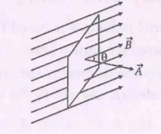
Do not measure from the surface itself; it is the angle between and the area vector .
Quick recap
- Magnetic flux through a surface is .
- For a uniform field, .
- The area vector is perpendicular to the surface and has magnitude equal to its area.
- The angle is between the magnetic field and the area vector.
- Flux is maximum for parallel vectors, zero for perpendicular vectors, and negative for opposite vectors.
Faraday’s Law of Induction
Faraday’s Laws of Electromagnetic Induction
Faraday’s law of induction — A changing magnetic flux through a coil or circuit induces an electromotive force (emf) in it.
The two laws
- First law: An emf is induced whenever the magnetic flux through a coil or circuit changes.
- Duration: The induced emf continues only while the magnetic flux is changing.
- Second law: The magnitude of induced emf is proportional to the rate of change of magnetic flux.
The minus sign indicates that the polarity of the induced emf is given by Lenz’s law.
For a coil of N turns, the net induced emf is N times the one-turn emf.
Quick recap
- A change in magnetic flux induces an emf in a circuit.
- Induced emf exists only while the magnetic flux is changing.
- The magnitude of induced emf is proportional to the rate of change of flux.
- For one turn, ; for turns, .
- The minus sign represents the polarity specified by Lenz’s law.
Lenz’s Law and Conservation of Energy
Lenz’s Law
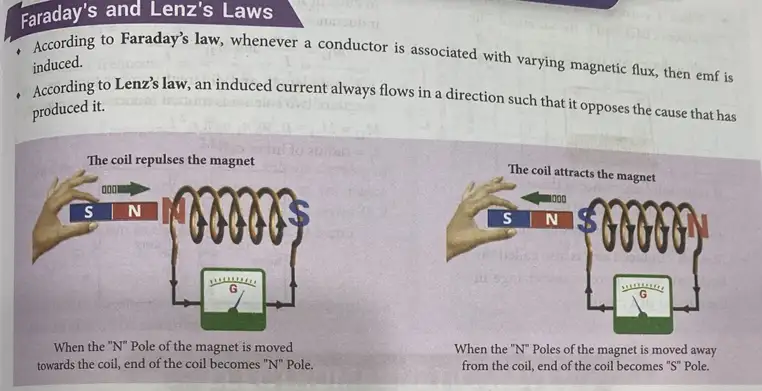
Lenz’s law — The induced current flows in a direction that opposes the change in magnetic flux that produces it.
The negative sign represents the opposition described by Lenz’s law.
How the law works
- Flux change: A changing magnetic flux induces an emf and, in a closed circuit, an induced current.
- Opposition: The induced current creates a magnetic effect that opposes the flux change—not necessarily the magnetic field itself.
- External work: Work must be done against the opposition to keep changing the flux.
- Energy transfer: The external work is converted into electrical energy in the circuit.
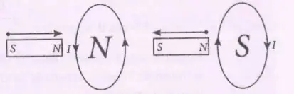
Magnet and Coil: Direction of Induced Current
| Magnet motion | Induced current (viewed from magnet) | Coil face toward magnet | How it opposes the motion |
|---|---|---|---|
| N pole approaches | Anticlockwise | North pole | Repels the approaching magnet |
| N pole moves away | Clockwise | South pole | Attracts the receding magnet |
Direction and Magnitude of Induced Emf
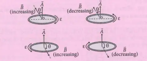
Factors affecting induced emf
- Coil resistance: The induced emf does not depend on the resistance of the coil.
- Relative speed: The magnitude of induced emf is directly proportional to the relative speed of the coil–magnet system.
Do not say the induced effect always opposes the magnetic field. It opposes the change in magnetic flux; the induced field may reinforce the original field when flux is decreasing.
How does Lenz’s law express conservation of energy?
A north pole approaches a closed coil. What is the induced current direction as viewed from the magnet, and why?
Quick recap
- Lenz’s law says induced current opposes the change in magnetic flux that produces it.
- The negative sign in Faraday’s law represents this opposition.
- A north pole approaching a coil produces anticlockwise current as viewed from the magnet; moving away produces clockwise current.
- External work against the induced magnetic effect becomes electrical energy in the circuit.
- Induced emf is independent of coil resistance and directly proportional to the relative coil–magnet speed.
Motional Electromotive Force
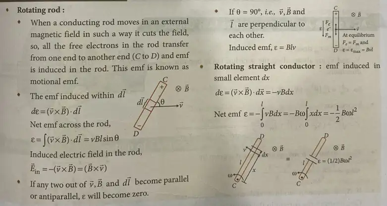
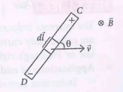
Motional Electromotive Force
For a straight rod in a uniform field perpendicular to the plane of and the rod, is the angle between the rod and its velocity.
Methods of Producing Induced EMF
For constant area and orientation, the emf depends on the rate of change of the magnetic field.
For constant and , changing the area inside the field induces an emf.
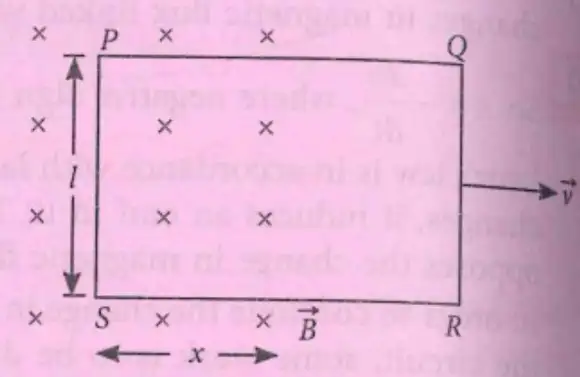
Rectangular loop moving out of a magnetic field
- Area in the field: If the loop side is and length remains inside the field, the area inside is .
- Motion out of the field: As the loop leaves the field, decreases, so for outward speed .
- Induced emf: for this motion and sign convention.
- Maximum emf: The emf is maximum when ; the negative indicates that the loop's overlap with the field is shrinking.
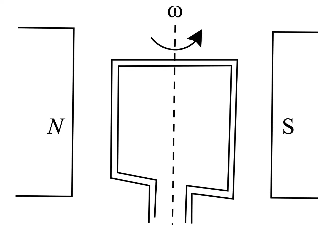
A coil with turns and area rotates at uniform angular velocity in a uniform field .
Rotating coil: key points
- Peak emf: is the maximum value of the induced emf.
- Alternating emf: The instantaneous emf varies sinusoidally with time and reverses direction periodically.
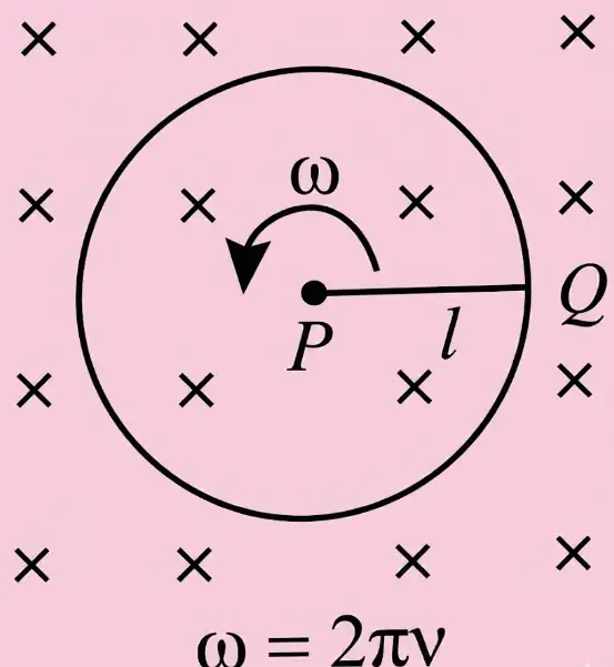
A rod of length rotates about one fixed end in a uniform magnetic field perpendicular to its plane of rotation. The signed result below follows the source's stated convention.
Rotating rod: key points
- Swept area: In one revolution the rod sweeps area ; its area-sweep rate is .
- Frequency: is the frequency of revolution, with and .
- Sign: The negative sign is for the source's chosen orientation and polarity; reversing the convention reverses the sign.
Eddy Currents
- Definition: Eddy currents are currents induced within a conductor when the magnetic flux linked with it changes.
- Direction: Find their direction using Lenz’s law or Fleming’s right-hand rule.
- Induction furnace: Uses the heating effect of eddy currents.
- Speedometer: Uses eddy currents to measure a vehicle’s instantaneous speed.
- Energy meter: Eddy currents are used to record electricity consumption.
Quick recap
- Motional emf arises when motion through a magnetic field separates free charges in a conductor.
- For a rod, ; in the stated geometry, with between the rod and velocity.
- Induced emf can result from changing magnetic field, circuit area or coil orientation.
- A rotating coil produces sinusoidal alternating emf with peak value .
- For a rotating rod, the signed emf in the stated convention is .
- Eddy currents are used in induction furnaces, speedometers and energy meters.
Inductance
Inductance and Self-Inductance
Inductance — A circuit property that opposes changes in current, analogous to inertia opposing changes in motion.
General properties
- Quantity: Inductance is a scalar; its SI unit is the henry ().
- Dimensions: .
- Opposition: An inductor resists a change in current, not a steady current.
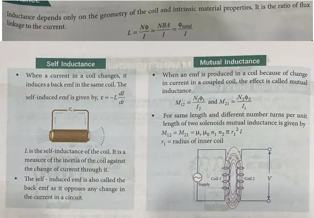
Self-induction — The production of an emf in a coil due to a change in its own current is self-induction; the property responsible is self-inductance.
Self-inductance of a coil
- Cause: Changing current changes the magnetic field and flux linked with the coil, inducing an emf and current.
- Lenz’s law: The induced current opposes the change in flux that produces it.
- Flux relation: For a given coil, total flux linkage is proportional to current: .
- Constant current: If current is constant, flux is constant and no electromagnetic induction occurs.
- Current change: produces self-induction.
Here is the number of turns and is flux through one turn; for a uniform field perpendicular to area , .
The minus sign represents Lenz’s law: the emf opposes the change in current.
Solenoid and real inductor
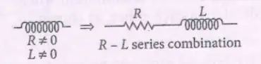
- Meaning of : It measures a coil’s resistance to a change in its current.
- Real inductor: Model it as an ideal inductance in series with resistance .
- Steady current: When current is constant, the inductor has no induced emf; its inductance still exists.
Here is turns per unit length and is the solenoid volume; is the relative permeability of its core.
Mutual Inductance
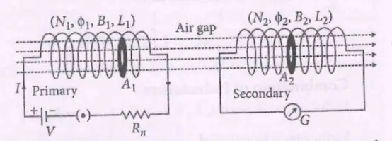
Mutual induction — The production of an emf in one coil due to a change in current in a coupled coil is mutual induction; the coupling property is mutual inductance.
Mutual inductance of two coils
- Flux linkage: With primary current held constant, secondary flux linkage is proportional to : .
- Changing primary current: changes the primary field and flux linked with the secondary, inducing an emf there.
- Air gap: In the stated arrangement, the flux linked with the secondary is less than the primary flux: .
- Reciprocity: Mutual inductance is the same whichever coil acts as primary: .
Here is flux through one turn of coil due to current in coil . The minus sign expresses Lenz’s law.
Each definition uses flux linkage in the coil whose turns are counted, due to current in the other coil.
Mutual Inductance for Common Coil Geometries
For two co-axial solenoids of common length and common cross-sectional area .
For two solenoids of the same length, is the radius of the inner coil.
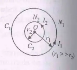
For an outer coil of radius and an inner coil of radius , where , use the outer coil’s field at its centre.
| Factor | Effect on |
|---|---|
| Number of turns | More turns in the two solenoids increase mutual inductance. |
| Common cross-sectional area | A larger common area increases mutual inductance. |
| Separation | Greater separation reduces linked flux and therefore reduces . |
| Relative orientation | is greatest when primary flux links the secondary fully; it is least when the coils are perpendicular. |
| Core permeability | A change in the magnetic permeability of the core changes mutual inductance. |
Energy Stored in an Inductor
Energy transfer
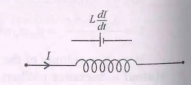
- Induced emf: A time-varying current in an inductor produces a self-induced emf.
- Power supplied: The source supplies power against the inductor’s emf; integrating this power as current rises gives the stored energy.
For current changing at rate .
The energy supplied during time is .
For an inductor carrying current .
Combination of Inductors
The equivalent inductance is the sum of the individual inductances.
For inductors in parallel without mutual coupling.
Series inductors with mutual coupling
- Coupled pair: For two series inductors with mutual inductance , each induced emf has self-induced and mutually induced contributions.
- Series aiding: When the mutual emfs aid each other, the total induced emf is .
The result applies when the mutual effects aid each other.
Growth of Current in an LR Circuit
Current growth
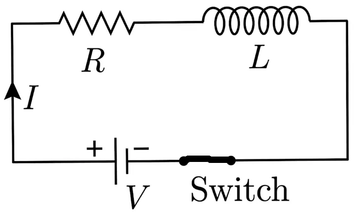
- Circuit equation: For a source of emf , resistance and inductance , .
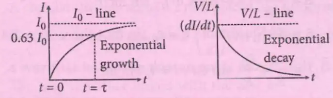
- Growth: After the switch is closed, current rises exponentially toward its steady maximum.
- At : Current is zero; the inductor behaves like an open circuit and provides effectively infinite opposition to the instantaneous change.
- At long times: Current becomes constant, the induced emf vanishes, and the inductor behaves like a short circuit.
- Peak current: ; it does not depend on .
Here is the steady current and is the time constant.
Growth time constant
- Definition: The time constant is the time taken for current to reach about of its final value.
- At : The current is approximately .
Decay of Current in an LR Circuit
Current decay
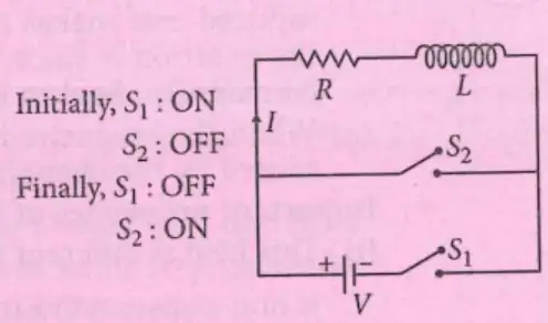
- Circuit equation: After the source is removed, .
- Decay: The current falls exponentially from its initial value toward zero.
- At : Current remains at immediately after switching.
- At long times: As , current approaches zero.
The decay time constant is the same as for current growth: .
Decay time constant
- Definition: The time constant is the time for current to fall to about of its initial value.
- At : The current is approximately .
What is self-inductance, and what is the self-induced emf?
State the current-growth and current-decay equations for an LR circuit.
Quick recap
- Inductance opposes changes in current; its SI unit is henry and its dimensions are .
- Self-induced emf is ; for a long solenoid, .
- Mutual induction occurs when changing current in one coil induces emf in a coupled coil; .
- Mutual inductance depends on turns, common area, separation, coil orientation and core permeability.
- An inductor stores energy , with supplied power and incremental energy .
- Uncoupled series and parallel inductors follow the sum and reciprocal-sum rules; series-aiding coupled coils have .
- In an LR circuit, current grows toward or decays toward zero with time constant ; at one time constant the values are about and , respectively.
AC Generator
AC Generator: Purpose and Parts
AC generator — A device that converts mechanical energy into electrical energy in the form of current that regularly alternates direction.
Essential parts
- Parts: Armature, field magnets with north and south poles, slip rings and brushes.
Principle and Working
Electromagnetic induction — A change in magnetic flux linked with a coil induces an emf, which lasts while the flux continues to change.
Generator operation
- Working: A wire loop rotates in a magnetic field, so the magnetic flux linked with it changes periodically.
- Direction: Fleming’s right-hand rule gives the direction of induced current.
- Output: The changing flux produces an alternating emf and current.
For a coil with turns, area , in magnetic field , rotating with angular speed , the flux linkage varies with time. Here, .
Faraday’s law gives the induced emf; its maximum value is .
For circuit resistance , the current varies sinusoidally with the emf.
Induced Electric Field
Induced electric field — A time-varying magnetic field induces an electric field that can drive charges even in a stationary conductor.
Properties
- Cause: Changing magnetic flux induces an emf; the associated electric field makes current flow.
- Non-conservative: Unlike an electrostatic field, its line integral around a closed path is non-zero.
- Work: A charge travelling once around the loop gains work equal to from the field.
- Force: The electric force on a charge is .
- Direction: The induced electric field points in the same direction as the induced current.
| Property | Induced electric field | Electrostatic field |
|---|---|---|
| Origin | Changing magnetic field | Stationary charges |
| Closed-path integral | Non-zero | Zero |
| Nature | Non-conservative | Conservative |
This relation applies when the integration path is stationary.
By symmetry, the field has equal magnitude everywhere on the circular path and is tangential at every point. Here, is the loop length and is the area in which the magnetic field changes.
State the principle of an AC generator.
Why is the induced electric field non-conservative?
Quick recap
- An AC generator converts mechanical energy into alternating electrical energy.
- Its essential parts are the armature, field magnets, slip rings and brushes.
- A rotating coil has flux linkage .
- The induced emf and current vary sinusoidally: and .
- A changing magnetic field induces a non-conservative electric field, including in a stationary conductor.
- For a stationary closed path, .
NEET Physics — ALL CHAPTERS
1
Basic Mathematics
2
Units and Measurement
3
Motion in a Straight Line
4
Motion in a Plane
5
Laws of Motion
6
Work, Energy and Power
7
System of Particles and Rotational Motion
8
Gravitation
9
Mechanical Properties of Solids
10
Mechanical Properties of Fluids
11
Thermal Properties of Matter
12
Thermodynamics
13
Kinetic Theory
14
Oscillations
15
Waves
16
Electric Charges and Fields
17
Electrostatic Potential and Capacitance
18
Current Electricity
19
Moving Charges and Magnetism
20
Magnetism and Matter
21
Electromagnetic Induction
22
Alternating Current
23
Electromagnetic Waves
24
Ray Optics and Optical Instruments
25
Wave Optics
26
Dual Nature of Radiation and Matter
27
Atoms
28
Nuclei
29
Semiconductor Electronics: Materials, Devices and Simple Circuits